OBD2 Reader; Redesigned... Part 3 - Writing Firmware the easy way
This is the 3rd part of this series of redesigning an OBD2 Reader into something else.
First let us recap on the previous post here:

In the previous post, we started writing our own firmware for the device using CubeMx and KeilV5, this was great until:
1: I learned that there was a super easier way (I am lazy by nature)2: I am a super shit coder that does not understand C very well, things became difficult.
This then lead me down a route I wish that I found a lot earlier.


STM32Duino is perfect for my level of coding knowledge and experience. This project really helped me get to grips with things quickly and tbh, who hasn’t coded for a Arduino before! The stars were aligning!
Again, I will start from the very beginning with the NEW firmware. and take it to a place i hope people will find it beneficial.
What pushed me down this route was the comfortability i had with Arduino and simplicity behind the whole libraries and environment.
LET'S GET STARTED!
First off, here is a link to the official guide from STM32Duino, but I’ll go through it here too: https://github.com/stm32duino/Arduino_Core_STM32#getting-started
From the first blog, we know we can reprogram the OBD2 reader and we know what pins to use.
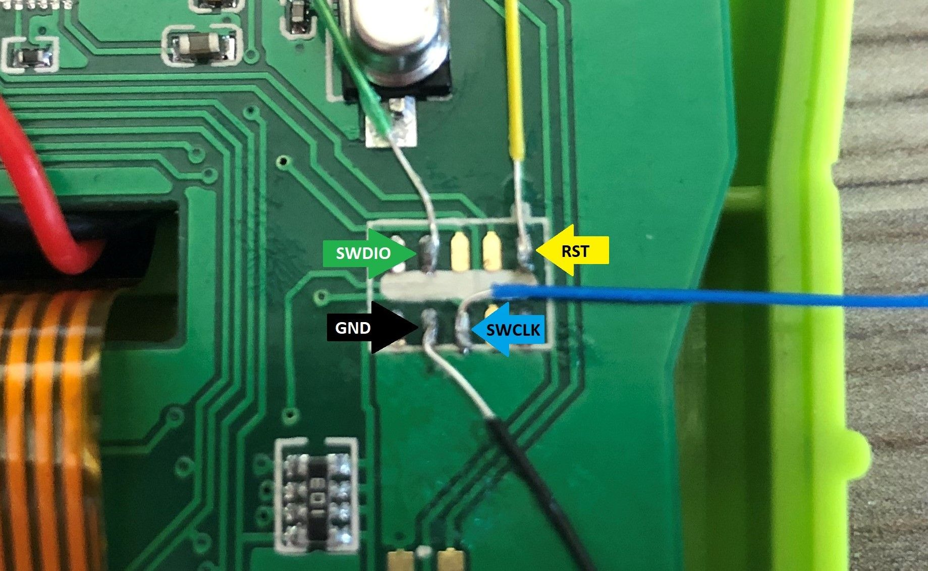
Attach these to the STLinkV2 and your good to go!
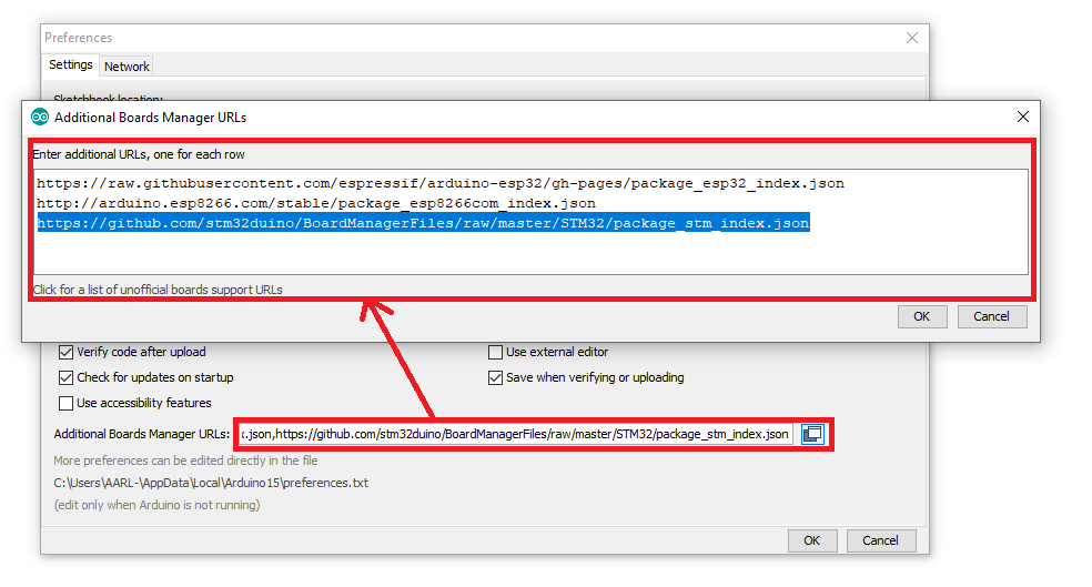
Next up, Open the Arduino IDE, Add the JSON link to the Additional Boards Manager URLs
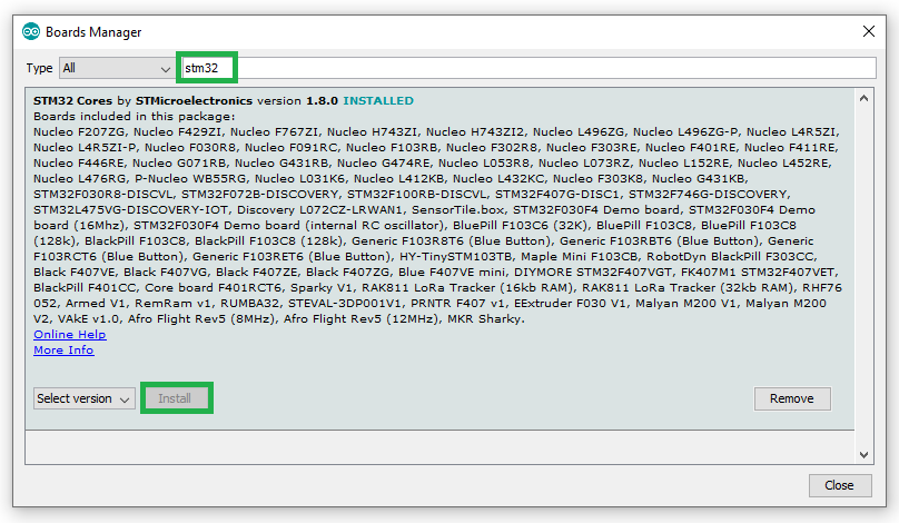
Once done, open the Boards Manager and search for "STM32" and install the STM32 Cores option.
This will now give you a list of all available boards that can be programmed. In our case for the JD101 (and a lot of other OBD2 readers) we can select the correct "Generic STM32F1 Series" based board (RED Highlight).
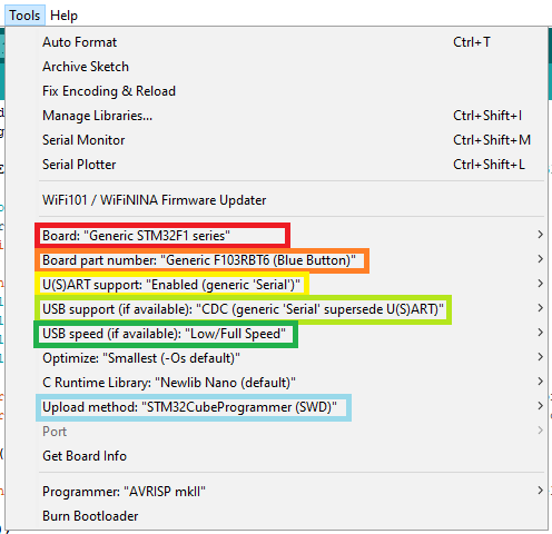
Then select the variant of chipset, in our case it is a "Generic F103RBT6" (Orange Highlight).
Make sure that you have "Enabled (Generic 'Serial')" (Yellow Highlight) and “CDC (Generic 'Serial')" (Lime Highlight) for UART features over USB.
For this specific device I had to select "USB Speed" as "Low/Full Speed" (Green Highlight).
Then select the upload method, this for me, as were using the STLinkV2, was SWD (Blue Highlight) via the STM32CubeProgrammer (as featured in the previous post).
We can now write our first bit of code to see if the device works with STM32Duino based firmware.
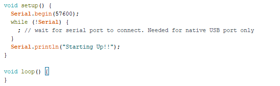
This simple application with let use connect to the device using UART over USB, and see an output.
So let's compile and upload to the device
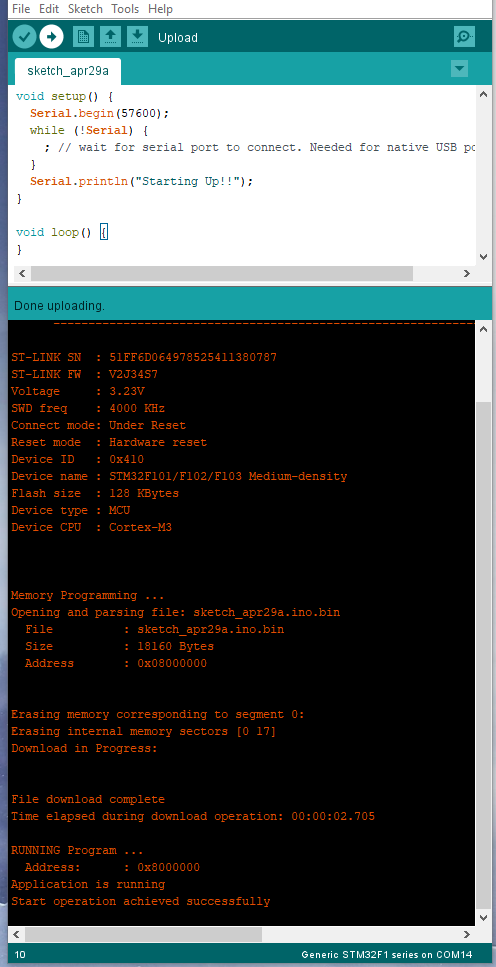
And when we plug the device in, select the COM port used, and run the Serial Monitor.
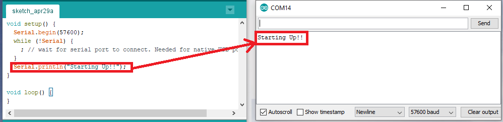
WE HAVE A WINNER!
Ok so lets talk about the real reason why i chose to go this route..
U8g2!
olikraus
Having used this library in the past for some tiny LCD screens, i wondered if it covered the right display driver for my needs.
First, let's go back to the LCD screen and its Data sheet
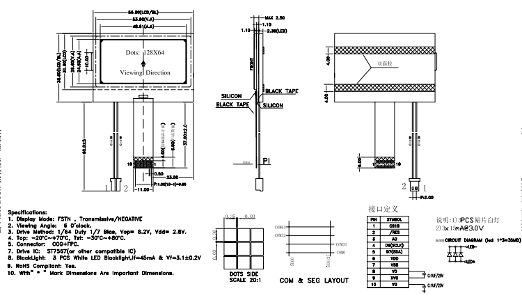
ST7567! This! This has/was my headache with the CubeMX/KeilV5 Route from before, i just couldn't get a driver working. However, The U8g2 Arduino Library had been proven to work with a number of ST7567 displays.
When using the U8g2 library you have to select what display constructor to use and what pins are allocated.
Because we don't have the freedom to select any pin, we have to use the ones we know that are connected.

Now lets select a constructor!
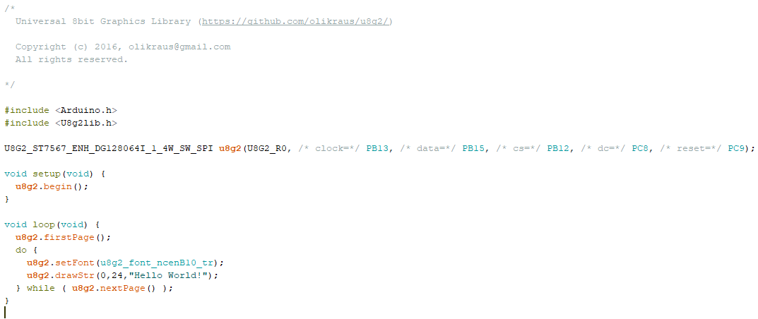
I narrowed the selection down to ST7567 devices and that were 4Wire SW_SPI (software SPI) based.
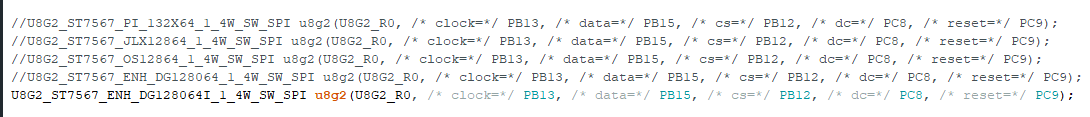
After compiling some simple code from the examples provided. i got a decent output to the screen! however, it was upside down.
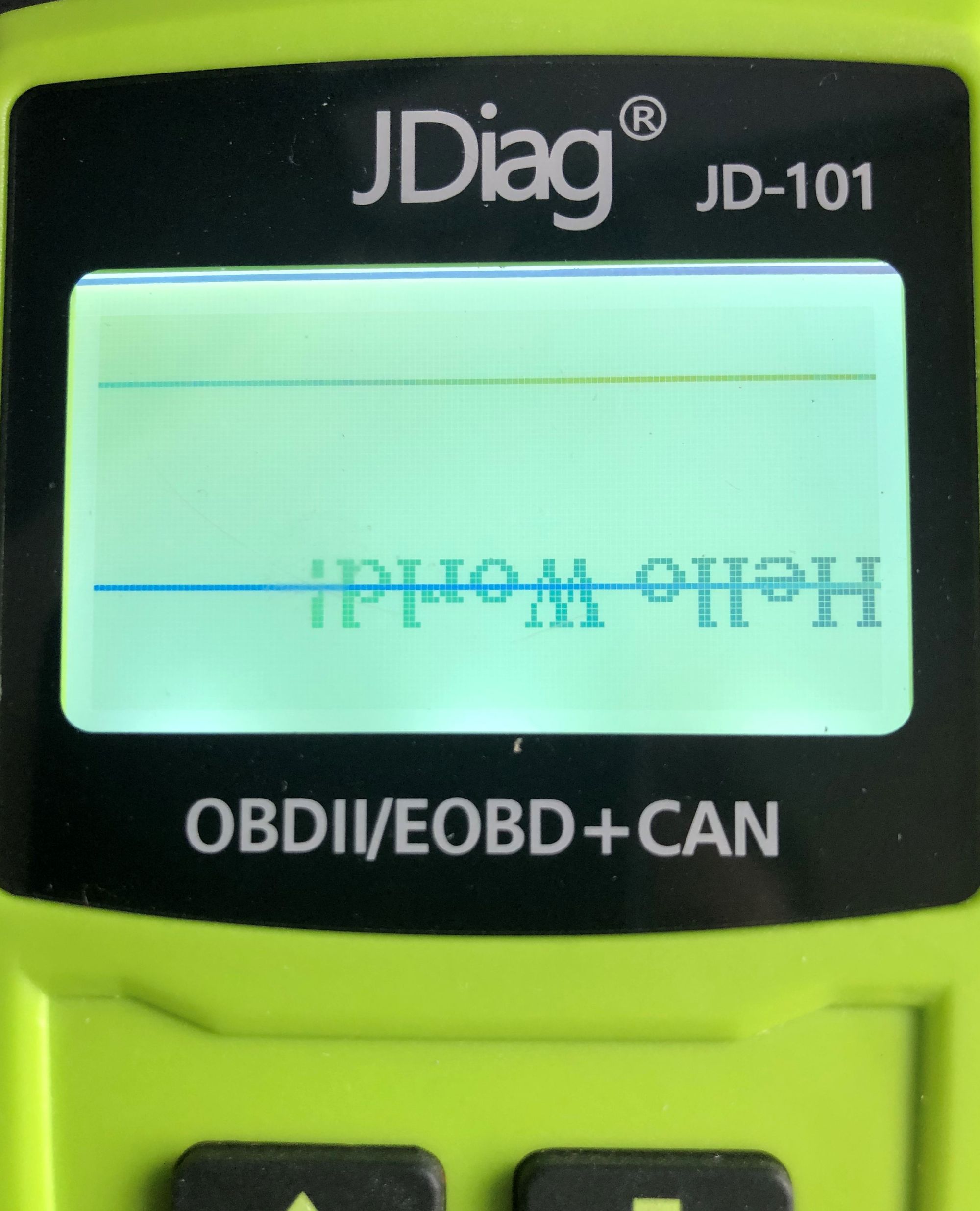
A simple change on the constructor line, sorts that right out!
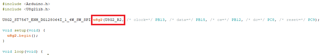
Perfect!
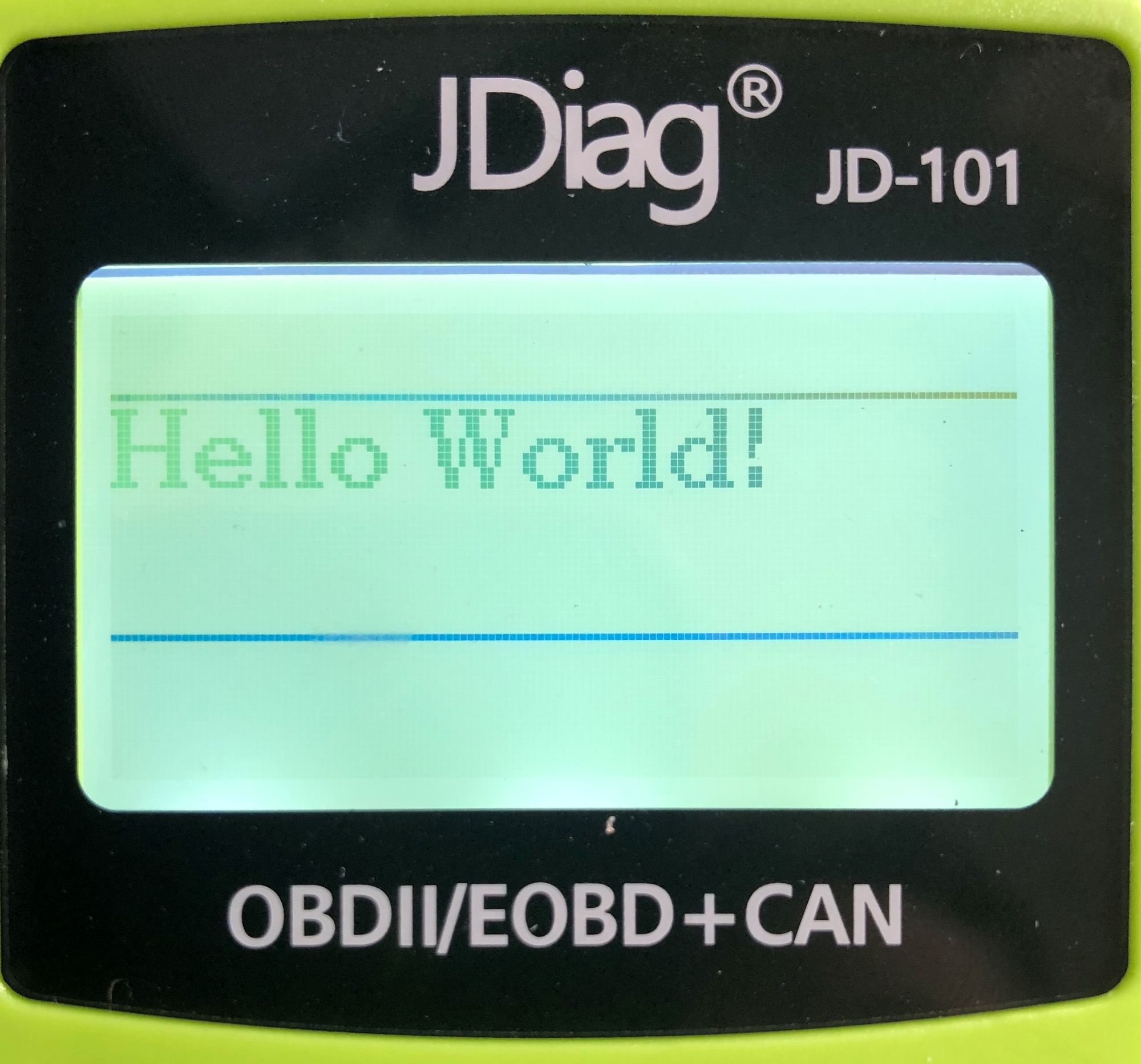
Please excuse the double horizontal lines across the screen, this was my fault by taking the screen apart and now they are there forever apparently, I can live with that for now. Lets expand on what we have and get some buttons working!
WOOOOOOOOT!
So can we expand on this. Well... yes we can.
We can get use of the SPI flash! Winbond W25Q64JV
This memory chip has 8 Megabytes of space available and communicates via SPI (Serial Peripheral Interface). It also supports Dual and Quad SPI modes which allow for faster data through output, but here I’ll stick to simple SPI.
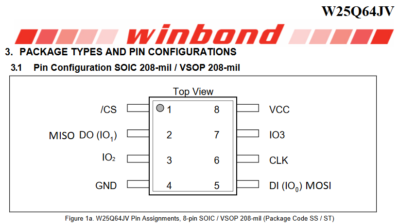
For the SPI flash, i needed to pinout and update my beautiful Paint drawn PCB trace. So i grabbed the data sheet for the SPI flash and mapped it out.
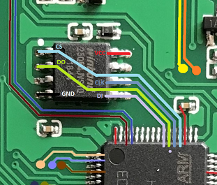
This gave me the pins i would need to be able to program the flash memory in the Arduino IDE.
//SPI flash Memory
  MISO = PA6
  MOSI = PA7
  CS = PA4
  Clock = PA5
The next step was to code some functions to read and write to the memory chip.
This was actually quite simple once i understood it: the microcontroller sends an instruction via SPI and then (depending on the instruction), reads or writes data.
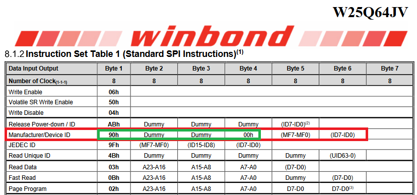
The commands are explained in the datasheet (available here: https://www.winbond.com/resource-files/w25q64jv spi revc 06032016 kms.pdf).
Instructions vary in length from a single byte to several bytes and may be followed by address bytes, data bytes, dummy bytes (don’t care), and in some cases, a combination.
So the first thing i wanted to try was to pull the "Manufacture ID" from the SPI flash. I would need to know what "Instruction" to send and what the "ID" should look like.
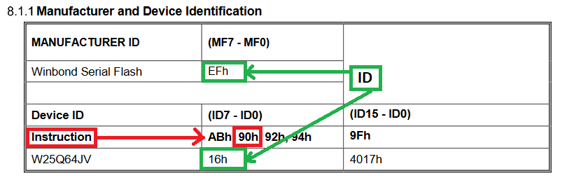
From the datasheet, we can see that the Instruction (Red Highlight) is 90 in hex (90h) and that the ID should return "EF16"!
So our instruction will look like this:
byte data [4]={0x90, 0xFF, 0xFF, 0x00};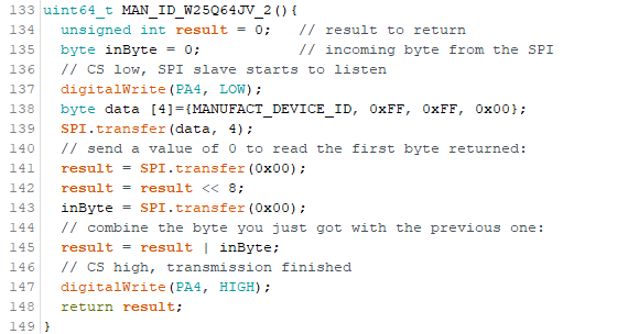
Here is the code to grab the Manufacturer Id from the SPI flash chip.
Once compiled and thrown at the device, i got it to output the value to the screen!
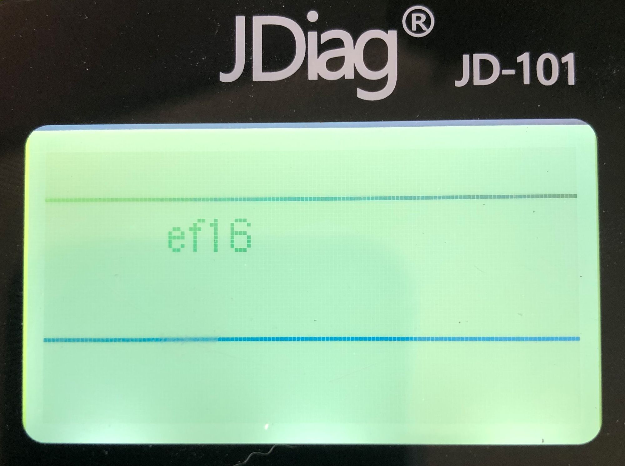
PERFECTO!
I did the same for the UNIQUE ID too
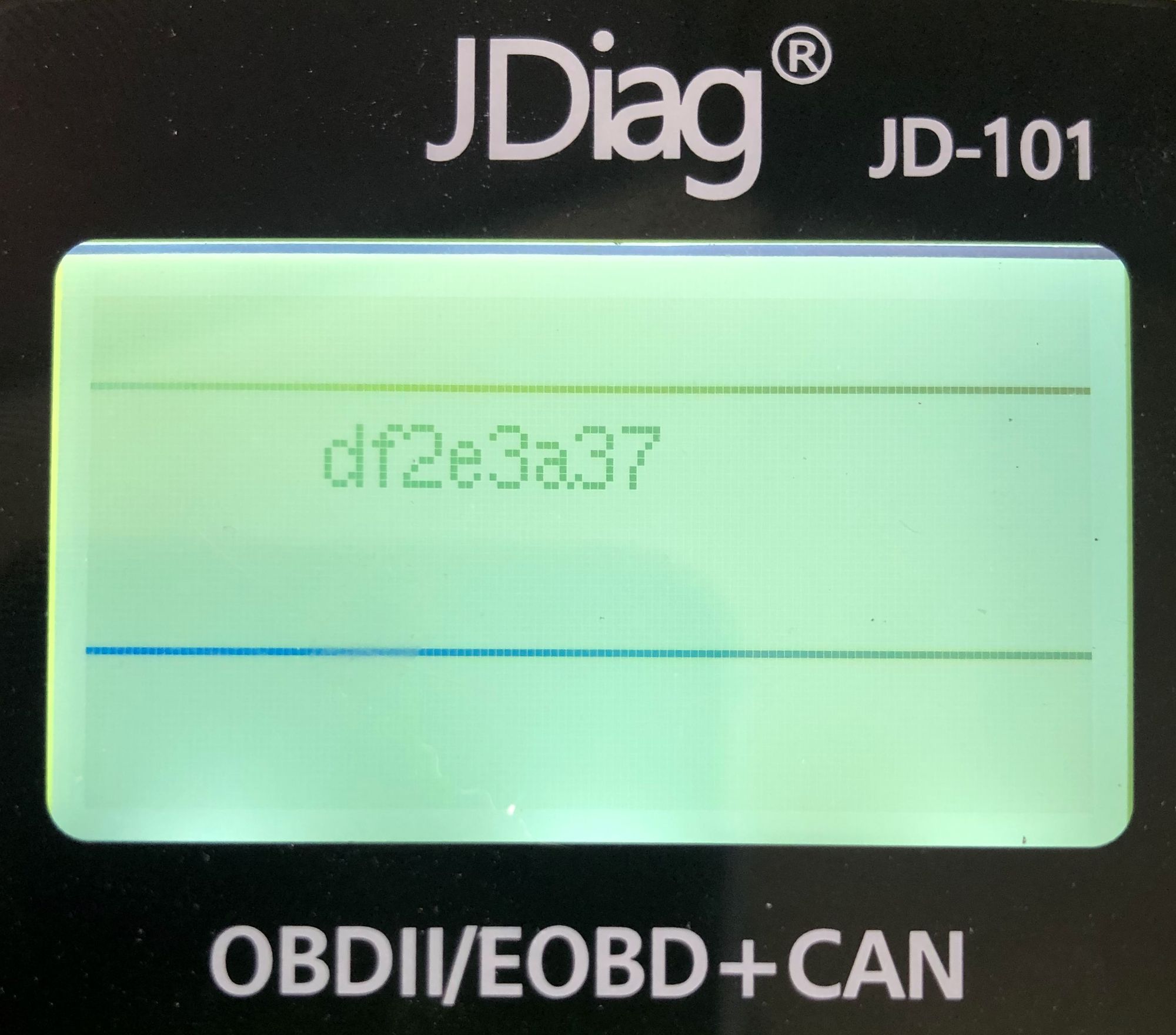
Now that we know we can use the SPI flash, i wanted to see what was stored on it, this however, i didn't print out to screen, i sent it to the Serial console instead.
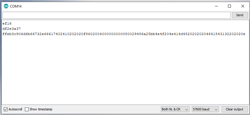
The first line is the Manufacturer ID. The Second is the Unique ID, and the Third is a 64byte dump at 0x000000 from the flash memory.
We throw that into a hex converter (i will do this in code at some point)
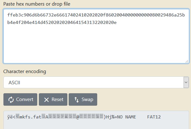
Ok nice, we can see that it does contain data, and its using a FAT 12 file system. (More info here: https://en.wikipedia.org/wiki/File_Allocation_Table#FAT12)
Now that i have managed to read the flash memory, lets see if we can write to it.
An important thing to consider when using flash memory is that you can’t just overwrite data with new data. That means, that in order to write into a specific location in the memory, the section has to be erased first.
So lets get to erasing the memory!
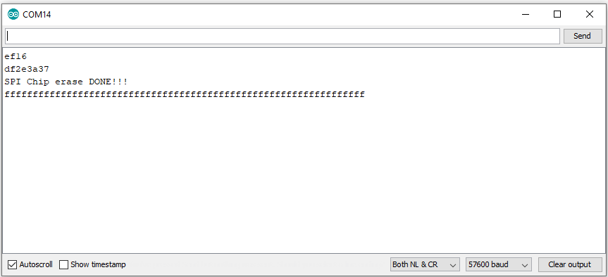
I reduced the SPI read down to 32 bytes because it didn't need to be massive to see all FFFFFF's
Chip erase takes around 15 seconds with a few small ass delays in there (needed)
OK, now lets write to the memory. We don't need to erase the whole chip every time, we just need to erase the space we are writing too.
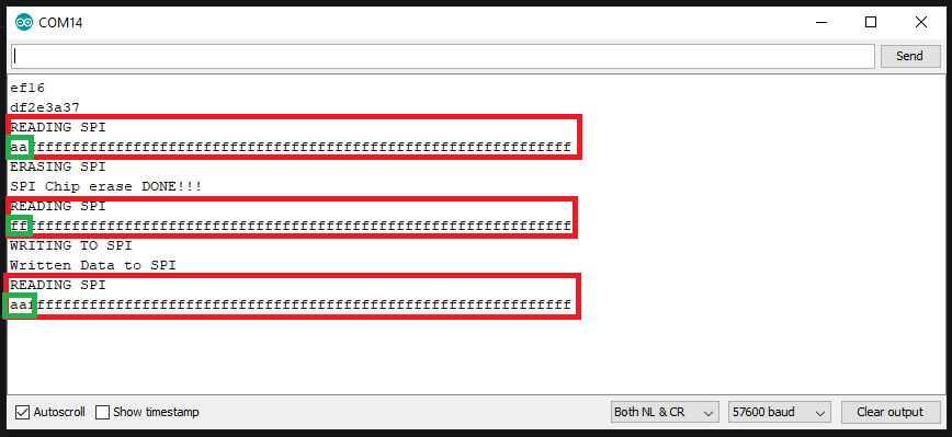
WINNNNNER, obviously, im only writing a small amount to the flash, but we can extend that up to 8MB of data if we want.
Secondly, in this example, i erase the chip each time, this is not needed and i will code a function to erase the sectors/pages needed to then be able to write too.
That's it for this blog post, i will continue to code for this device and take it to another level, and ive gotta have some evilness too. So stay tuned for next blog in the series.