
OBD2 Reader; Redesigned... Part 2 - Writing Firmware
This is the 2nd part of this series of redesigning an OBD2 Reader into something else.
First lets recap on the previous post here: https://noobiedog.com/odb2-reader-redesigned/
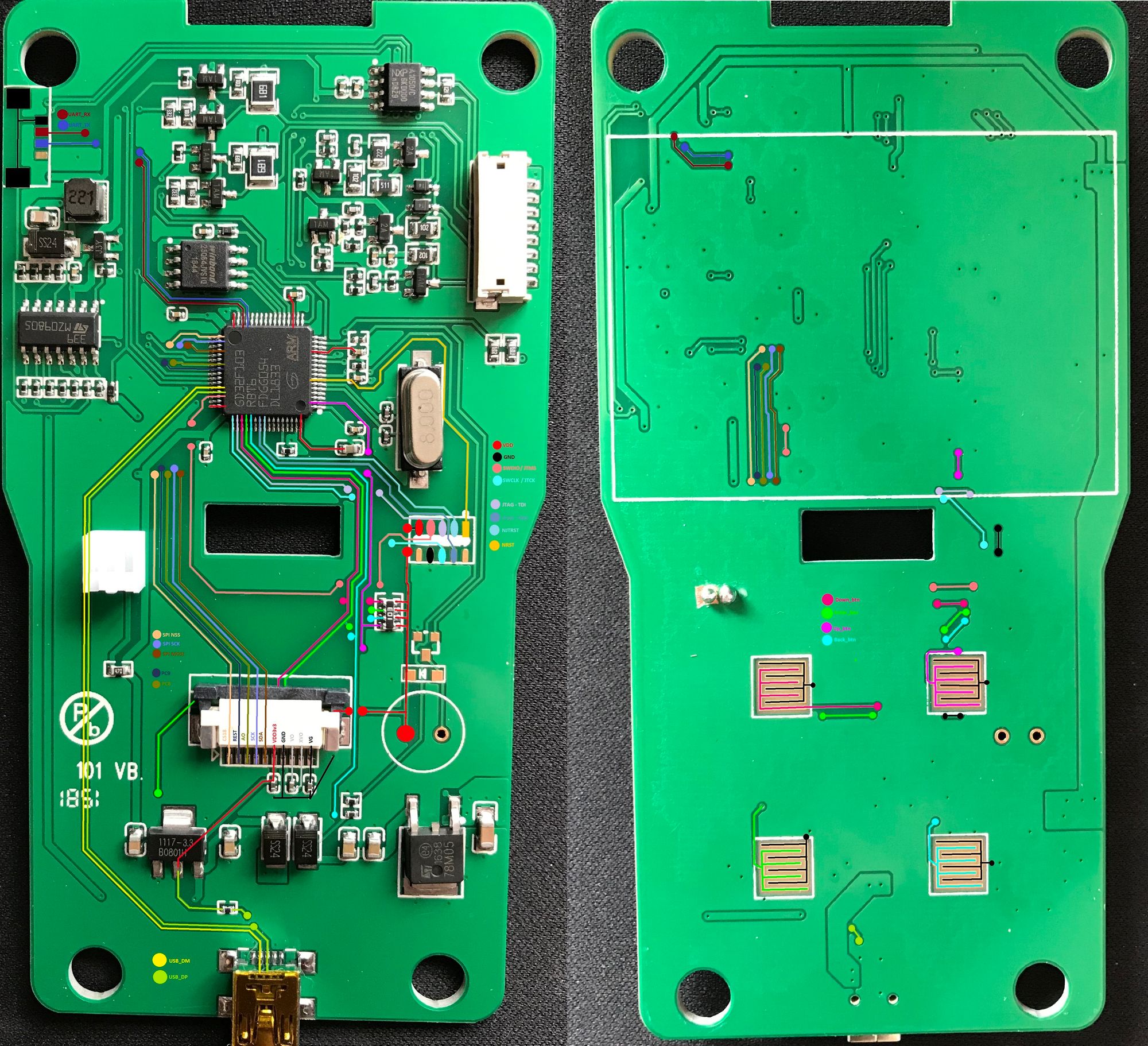
In the previous post, we decided on the OBD2 reader we would settle on, we had done a full pinout discovery on the board, got to know the hardware used and now on our way to write out own firmware.
I think this is a good point to tell you all that I’m NOT a "Software Coder/Programmer, Embedded Engineer, or Hardware Specialist", I’m sure there are a tonne of better blogs out there that cover writing firmware for the STM32/GD32 Chipsets. Please use a bit of Google Foo, you may come up with a better way!
So, the tools I’m going to use are:
STM32CubeMX (https://www.st.com/en/development-tools/stm32cubemx.html)
STM32CubeProgrammer (https://www.st.com/en/development-tools/stm32cubeprog.html)
KeilV5 MDK-ARM(https://www.keil.com/demo/eval/arm.htm)
Once all three are installed we can set about creating our own firmware, in the previous post, id already erased the original Firmware from the device, and this enabled CRP to be disabled.
Launching STM32CubeMX we are presented with what MCU or Board we would like to program for, now if you have any STM32 Dev boards knocking about, now is a great time to give some examples a go. it really is not that difficult, and you are not the first/only one to try things!
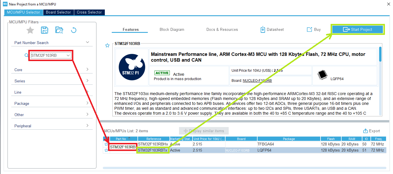
By entering the MCU ID in the Search area (RED) and selecting the correct model on the list (GREEN), we can "Start Project".
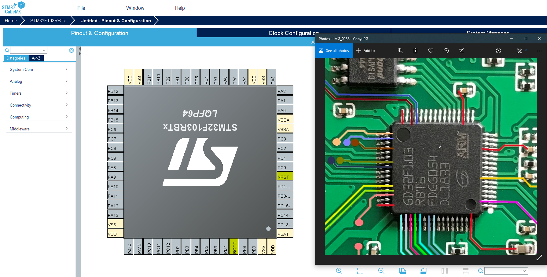
I orientated the MCU as it was in my images and pin layouts. This made it a bit easier to start populating the pins I would need. However, for this initial phase, I am going to keep it super simple and feed it the minimum to have some output.
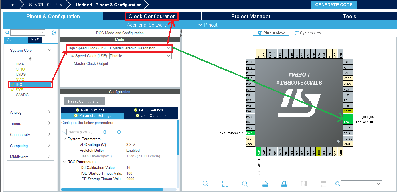
One of the first few things i have learnt to do when starting these project are:
1: Set the RCC to "Crystal/Ceramic Resonator"
2: Set the clock speed to 48Mhz
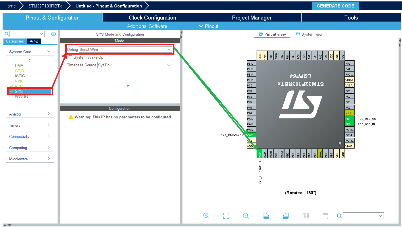
3: Set the SYS Debug Parameter to "Serial Wire"
This will assign pins for you where they should already be, as we can double check the pinout against the Pinout View.
I would now sort out my code settings in the "Project Manager" tab.
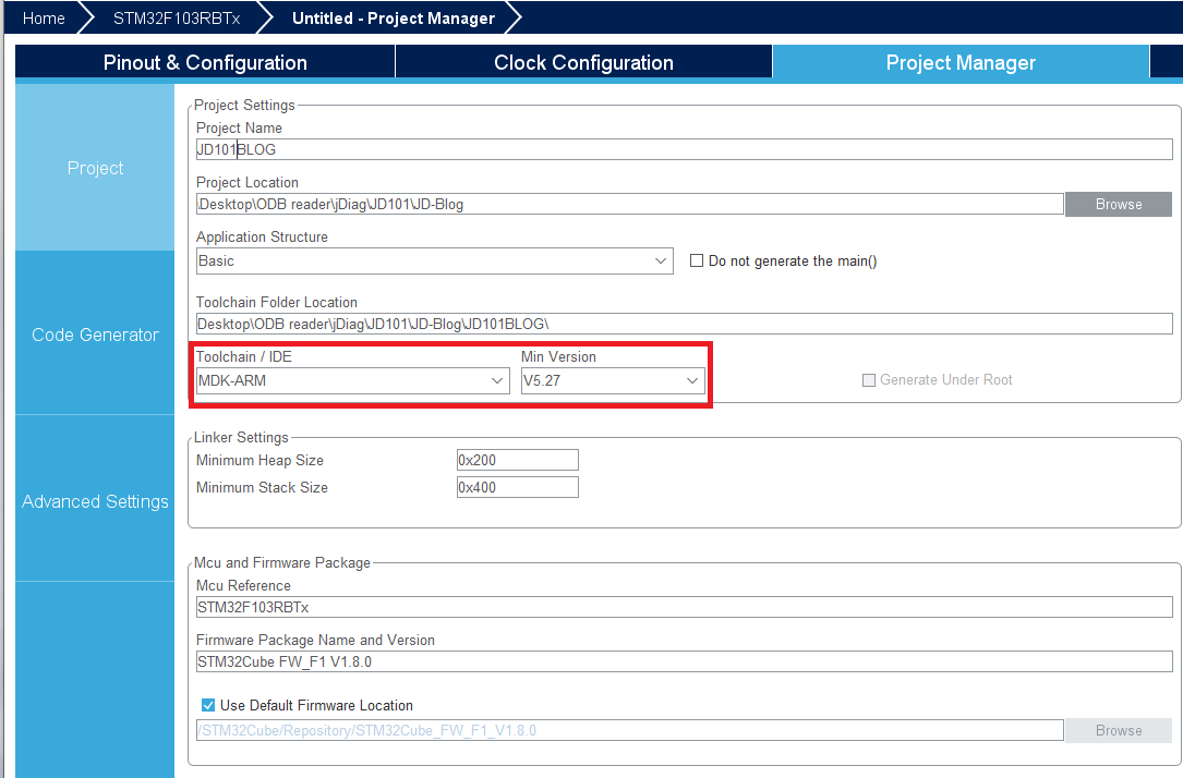
Here I am giving the project a name, location and what Toolchain/IDE I will be using. This is important for the compile and debug stage.
Once all that is done, I will just "SAVE" the project. and move on to assigning PINS!
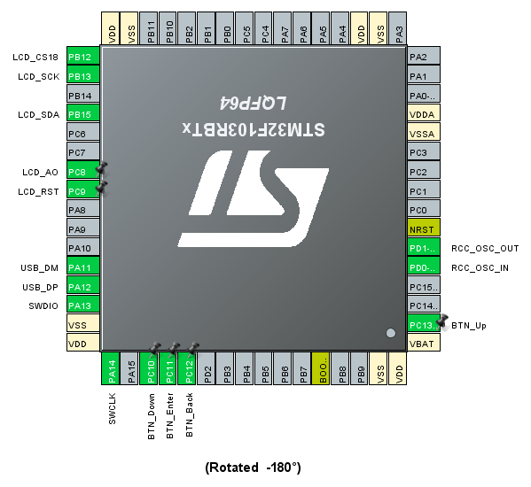
In the above picture I have enabled quite a few pins:
The Buttons (Up, Down, Enter and Back)
SPI with NSS enabled as an output
USB device capability (Virtual Com Port)
Things I have not enabled/sorted:
SPI Flash
CAN Transceiver
USART1/2/3
These will come at another time.
Now that the pins are assigned, we need to tell them what to do, a good way of doing this is getting the front device buttons working.
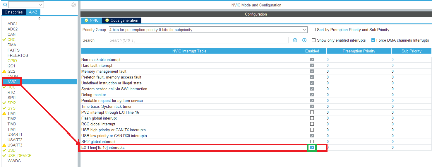
For the buttons you can set them as GPIO Inputs, or External Interrupts. I chose External Interrupts as I didn’t want them to work inside the "While Loop” ...
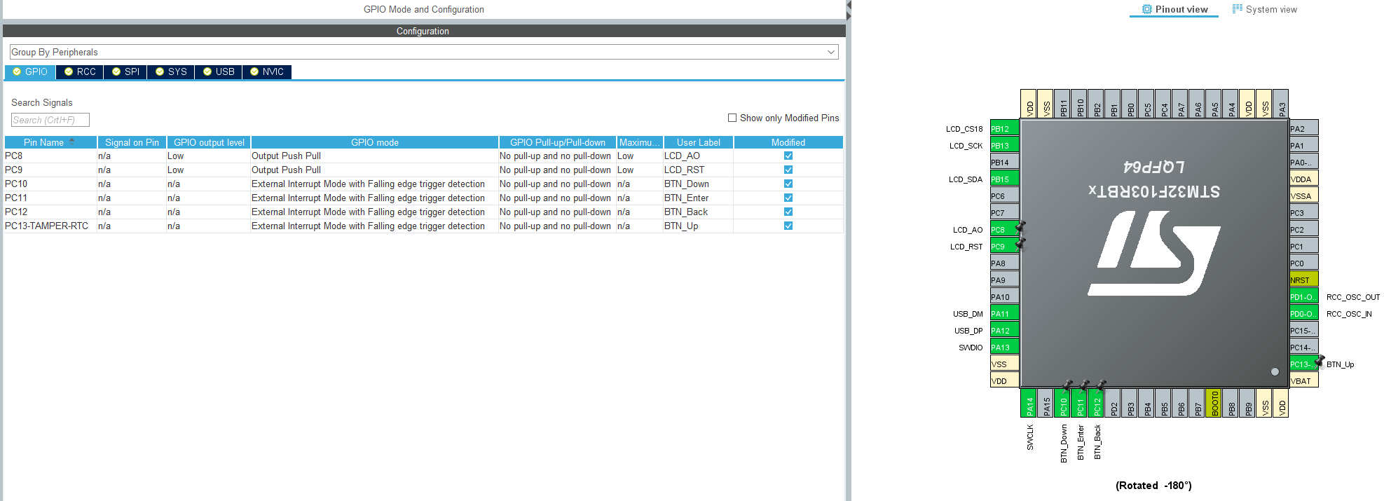
If you are setting pins as External Interrupts, then there is a setting you need to enable on the "NVIC" category.
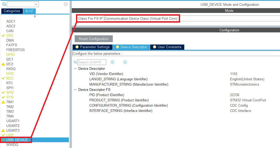
Additionally, to this, I wanted a way to debug (visually) what was happening, you know, the old "Debug Via Text" method ;)
So I changed the USB to a "Virtual Com Port" that allowed me to connect a serial console to the device and read any data I put to it.
Awesome. So, I think we are all set at this part to get the code generated and move over to the KeilV5 IDE.
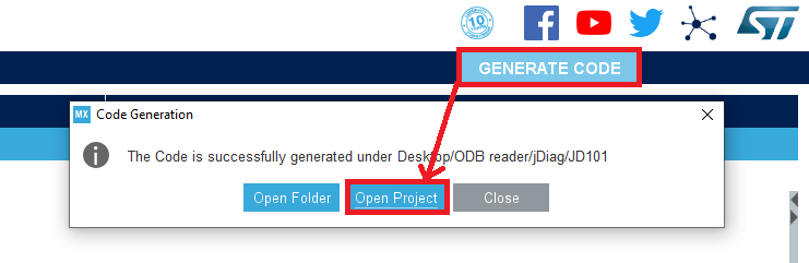
When you click "Open Project" it will open up KeilV5 with your project already populated.
The "main" file you’re going to edit is... main.c... see what I did there...
As you may notice, the file will be very populated for you already, and a lot of things do not need changing. There are areas to note. Anything that has a comment of "User Code Begin"/"User Code End" is where we will put our custom code. this is because if we need to add another pin or change a pin function, CubeMx will not overwrite our custom code.
So, we have the pins set to EXTI for buttons, we have the USB CDC Virtual Serial Port Enabled. Let us get some code running on the device!
First up. we need to link a header file for the use of a function called "CDC_Transmit_FS", this allows us to transmit data to the Serial console (USB Virtual Com Port", if this is missing, you will get a few errors.
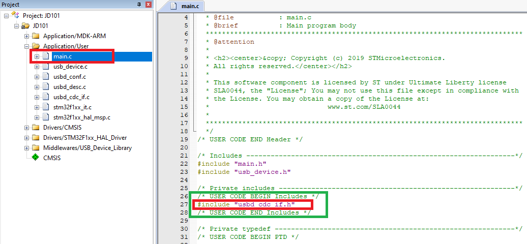
Winner. See how its placed between "USER CODE BEGIN/END" Comment tags...
Next up, let’s throw something into the "Main" Program Function.
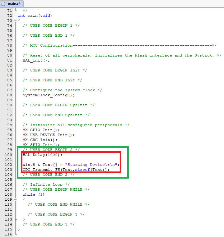
This will just print out "Starting Device" to the Virtual Serial Port via USB.
Simple really!
Next is to add some code for the buttons to do something, again, I want to keep it simple for now.
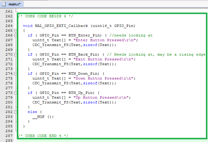
We use the "HAL_GPIO_EXTI_Callback" function to see when a button is pressed. However, as you can see from my comments, for some reason the "Enter" and "Back" buttons register as "UP” ... I suspect that there is a hardware design for this, and I am just missing something.
I will sort this out at a later stage, but what we want to see is when I press a button, it prints it to the serial console! So, let us build, check for errors or warnings, then upload to the device!
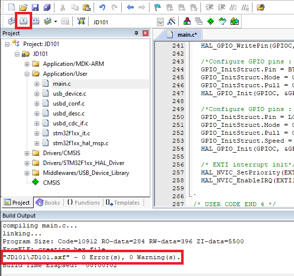
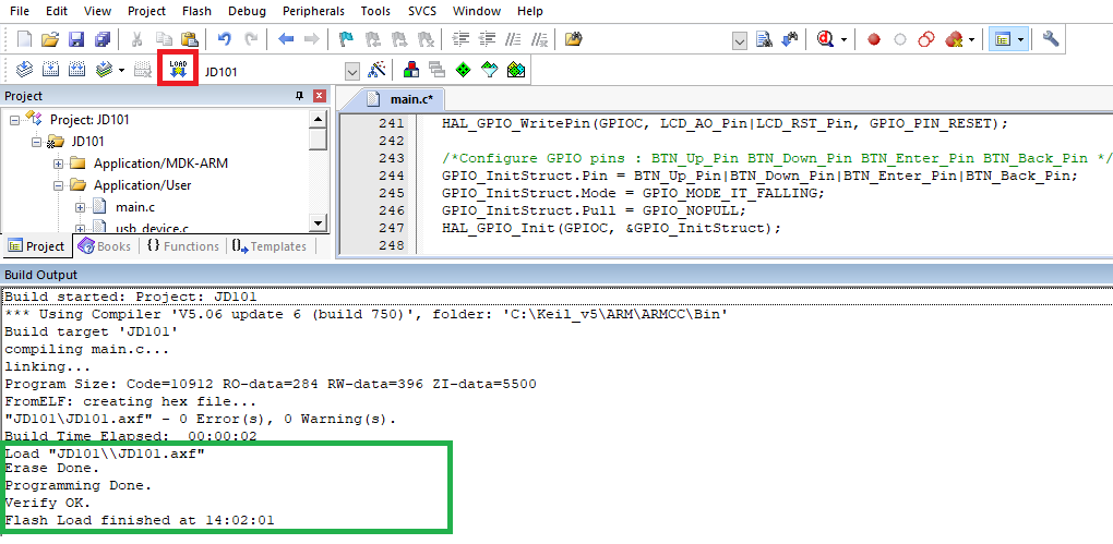
So, it builds fine, happy with that. now to upload to the device.
Now remembering how it was wired up to the STLinkV2 debugger board earlier, we use the same thing to program the board. but I would check the settings first.
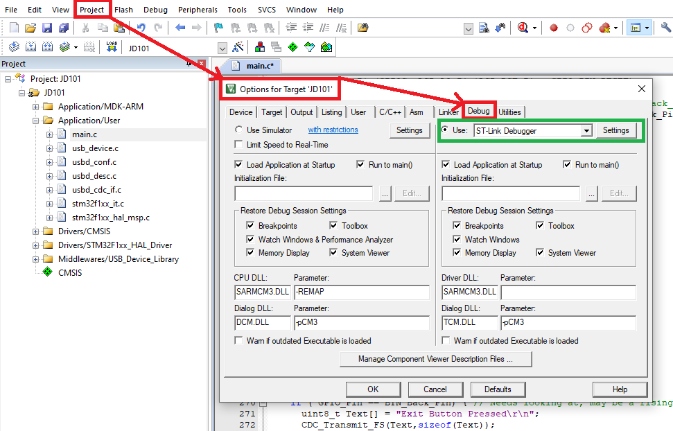
Once you have checked it can see the debugger and everything looks good, we can try to upload our flash to the device!
Now to see if our efforts are worth what we have done! Unplug the STLinkV2, and plug the OBD2 Reader into a USB slot and check for a Virtual Com Port
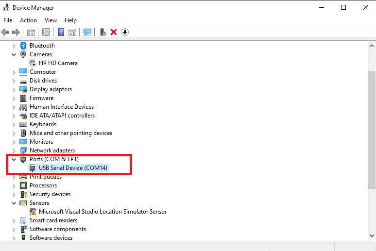
By using any serial console (I generally use Arduino's Built in Serial Monitor) we can try and see what is happening
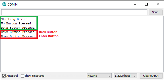
Ok! we get off to a great start, we can see where we wanted to see the main(); function start, and then button presses...
OK so here is where it all goes tits up for me.
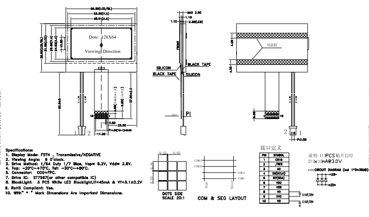
THE LCD SCREEN
The LCD screen that was in use on the, never came with any silkscreen to identify it, but like I said in the previous post, the screen worked on another device, this did have the details I needed.
I tried for about a week, trying to get this bloody screen to work with CubeMx/KeilV5 and had absolutely no success at all.
This part got me down for a while, and although I found an "EASIER" way, I feel like I cheated, and did not learn what I needed too.
So, for now, I have uploaded this simplistic firmware to GitHub here:
 NoobieDog
This is a great start to writing your own firmware for an unknown device, but I am going to shift over to another angle! something EVERYBODY can get into and most already have.
Part 3 Incoming ASAP!