
OBD2 Reader; Redesigned! Part 1 - The Device!
This project is a multipart blog post series. please find other parts below:
OBD2 Reader; Redesigned... Part 2 - Writing Firmware
https://noobiedog.com/odb2-reader-redesigned-part-2-firmware/
OBD2 Reader; Redesigned... Part 3 - Writing Firmware the easy way
https://noobiedog.com/odb2-reader-redesigned-part-3-writing-firmware-the-easy-way/
OBD2 Reader; Redesigned... Part 4 - Putting it all together!
https://noobiedog.com/obd2-reader-redesigned-part-4-putting-it-all-together/
Back in 2018, I had bought an OBD2 reader to scan the car I had at the time. But when the device turned up, I was intrigued to see what drove the device and how it worked.
This was the device I bought
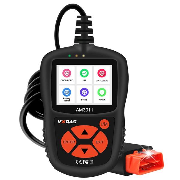
The VXDAS AM3011 OBD2 Scanner (https://www.vxdas.com/products/vxdas-obd2-scanner-obdii-auto-car-code-reader)
I had noticed it had a USB Mini port located on the bottom, and it had a few buttons on the front interface. Also, it had the OBD2 Interface plug to go into the cars. Upon opening the device, we can work out what is driving the screen/buttons and what capability the unit has
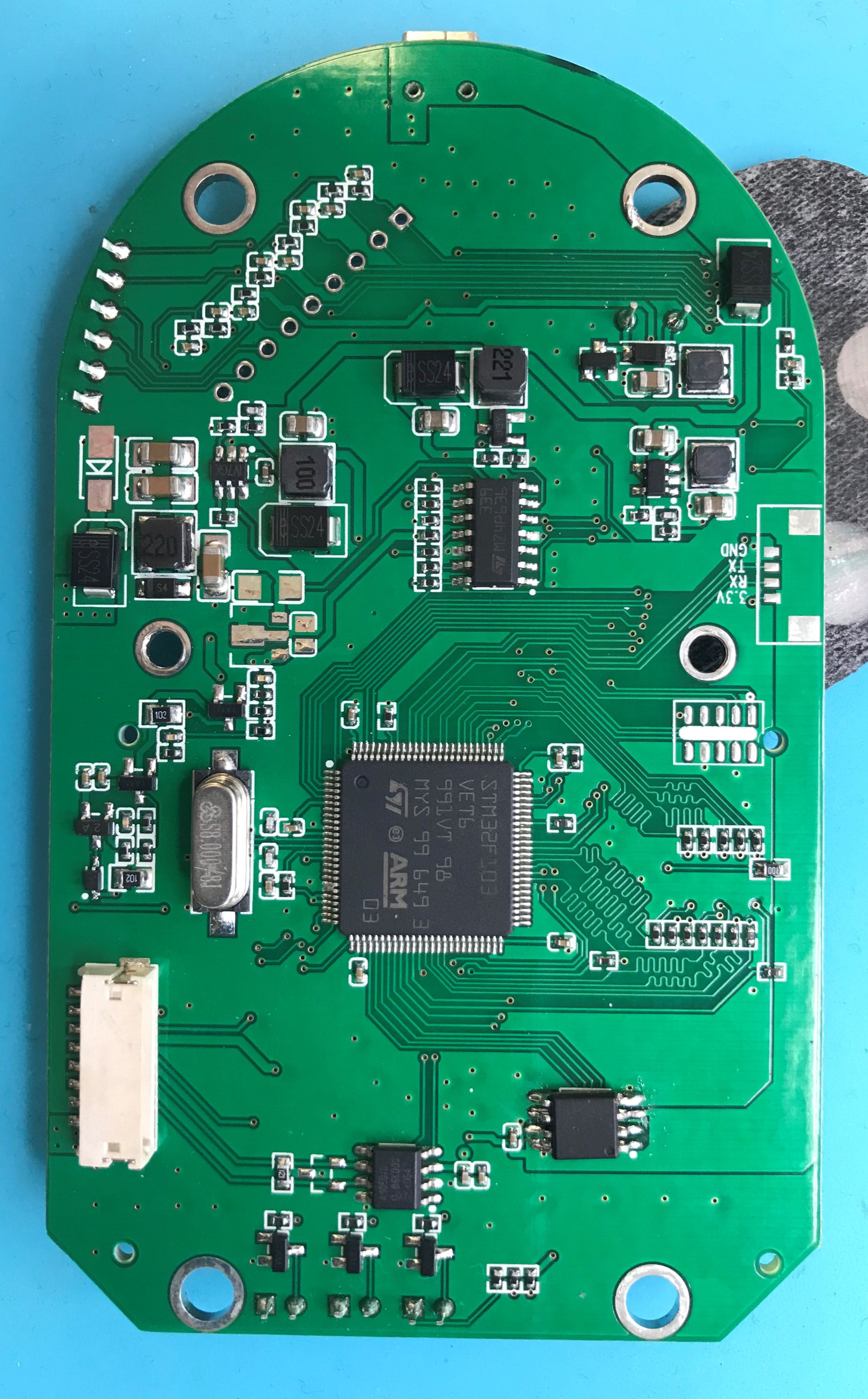
Initial observations are; there is a STM32F103 SoC, an SPI SOIC8 Flash, a few bits to take the 12V from the car down to 5v and 3.3v, USB data lines, a mini buzzer, a connector for the screen, some LEDs and a 6 pin ribbon cable for the buttons.
So overall not a great deal! but enough to do some things with it. First thing though was to see if we can get the Firmware OFF the device, to see what’s going on, if we could Reverse Engineer it or not.
At this time, I was not able to pull the firmware off the device. I spoke with my colleagues at the time (@Iskuri) and he pointed out that I would be able to erase the program and write my own!
:)
First, I wanted to get a good pin out and trace and work out what pins and PCB traces did what!
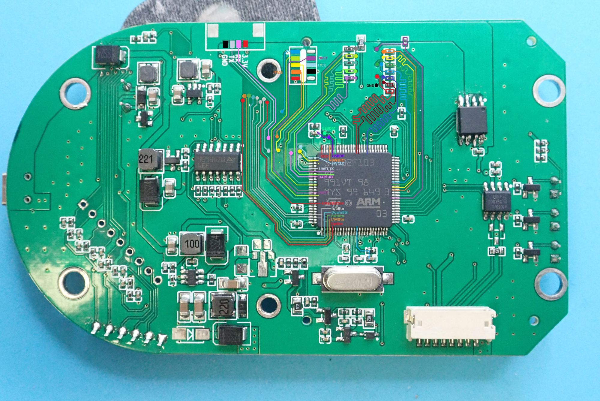
with additional help from the STM32F103 data sheet (pin out) I was able to get a new program onto the device, that when the device was plugged into a computer, it would act as a Mass Storage Device (MSD). This was great news and proven that I could create my own application for this device!
However, me in my infinite wisdom and stupidity, coded out the SWD functionality so bricked it!
I spoke to a few friends about the device, what I wanted to do, and Time Vs Effort was considered! It come down to this!
STM32F103 based SoC
4 or more buttons
LCD screen
SPI Flash
After looking up the device more, it was determined that it was a multi label device, made by JDiag and renamed/coloured where applicable. So, I went down a black hole trying to find some others to play with since I had murdered the OG one! Also, maybe, just MAYBE! one would have CRP disabled!
Next: I bought another device!
IsYoung NL100
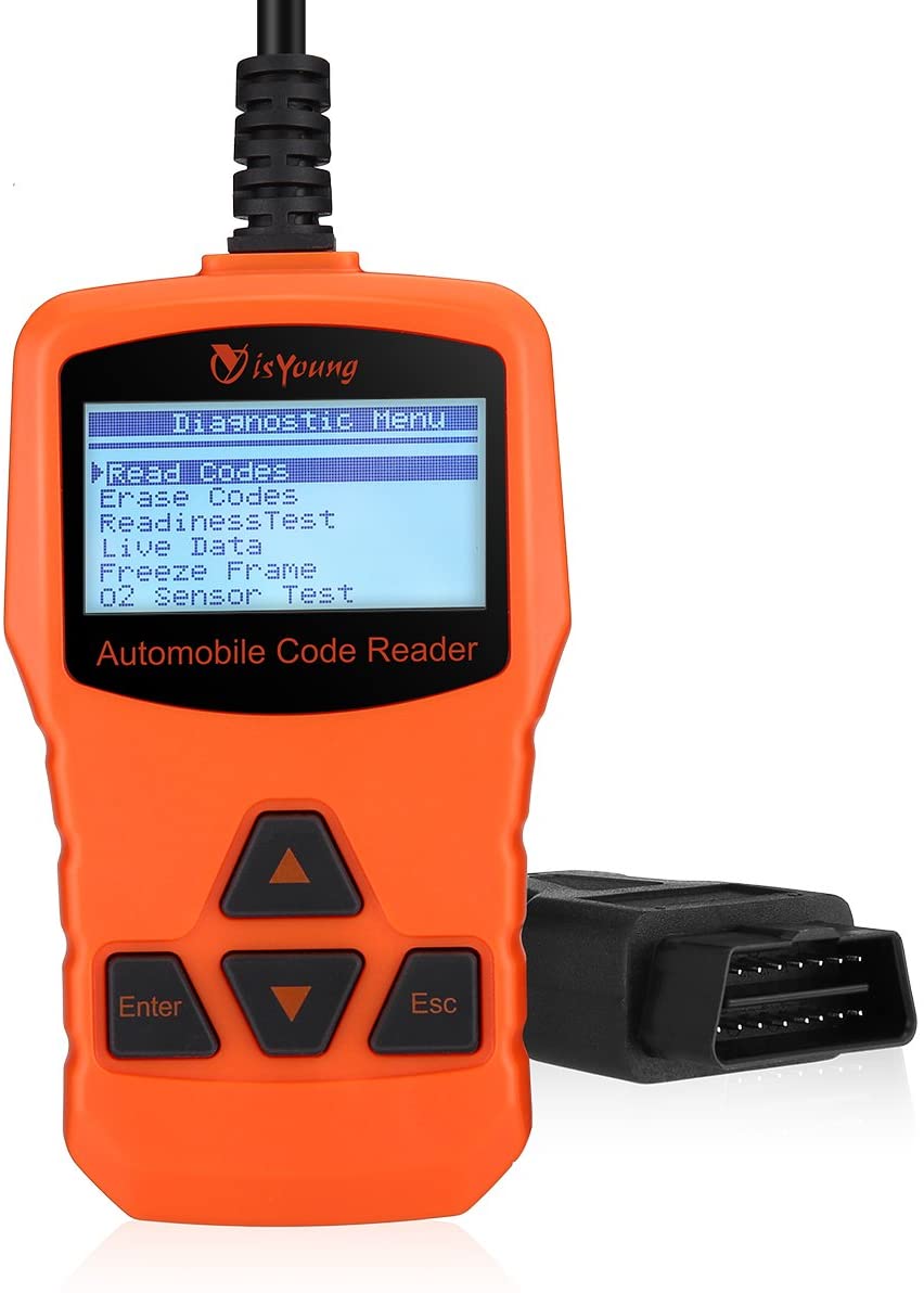
This from the start looked promising! However, it was not! (I’m sure it will be once I spend more time on it)
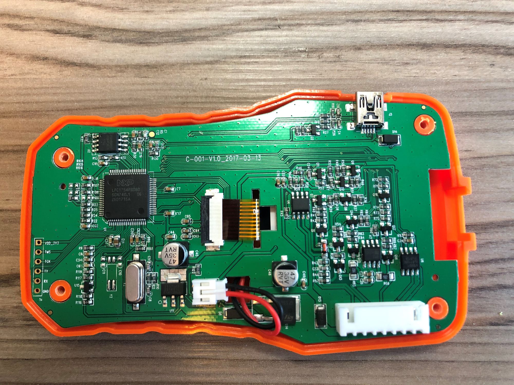
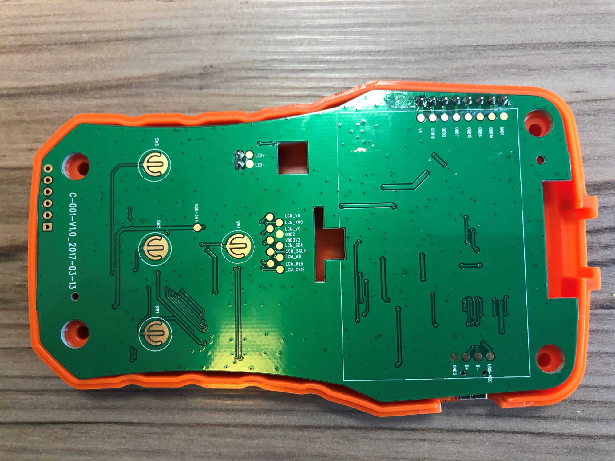
As you can see from the images, there is a tonne of useful info on here from the silk print, it gives us more pins for the debugging and screen, along with the OBD2 cable. This comes useful later on.
Secondly to this, the MCU is a NXP LPC 1754 (https://www.nxp.com/products/processors-and-microcontrollers/arm-microcontrollers/general-purpose-mcus/lpc1700-cortex-m3/scalable-mainstream-32-bit-microcontroller-mcu-based-on-armarm-cortex-m3-core:LPC1754FBD80). Just like the STM32, these are super easy to develop for.
I started by pulling off the SPI flash, just to get a read, but managed to ham-fist the chip and now it sits with a broken leg. this put the device out of action for now. I will replace the SPI with another chip and get to writing my own code for this device! this is now a side project for a different chip to STM32. An Ideal device to be honest!
At the same time, I had another device on order (ANCEL AD410) that was taking its time getting to my address. this one had a number of extras that I’m sure would be a next stage (colour screen, more buttons, etc.)
I reached out to @iskuri and talked to him about it, he said he would also like to do something along these lines of finding a device and repurposing it, he asked if it was ok to go down the same road, but at a slightly different angle!
This would be a fun split project! sharing info between devices and code.
I pointed Chris to the devices I had purchased and done work on, but nothing was hella fruitful as of yet! He looked around and found the one he would settle on.
At this point Chris went off and did his awesome work with the NFC Attack tool and Firmware extraction! He recently blogged about it here: https://www.pentestpartners.com/security-blog/turning-an-obd-ii-reader-into-a-usb-nfc-attack-tool/and also did a 44Con Talk on it here:
ANCEL AD410 OBD2/CAN Diagnostic Tool.
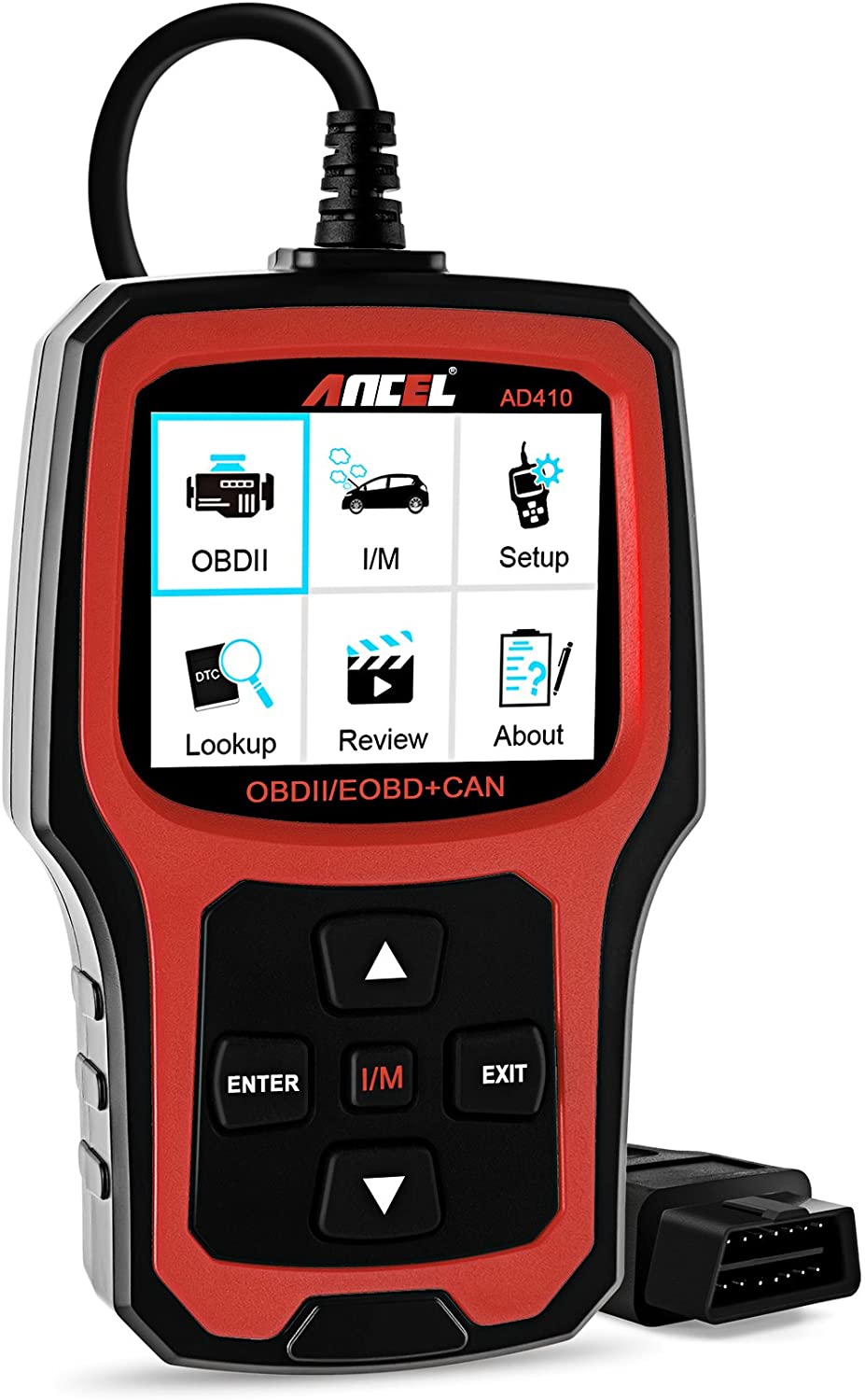
Upon opening the device, it has a lot more to it that the other devices, a fuck tonne more pins for the LCD too.
I mapped as much as I could out. Again, this device used the GD32F103 series of SoC.
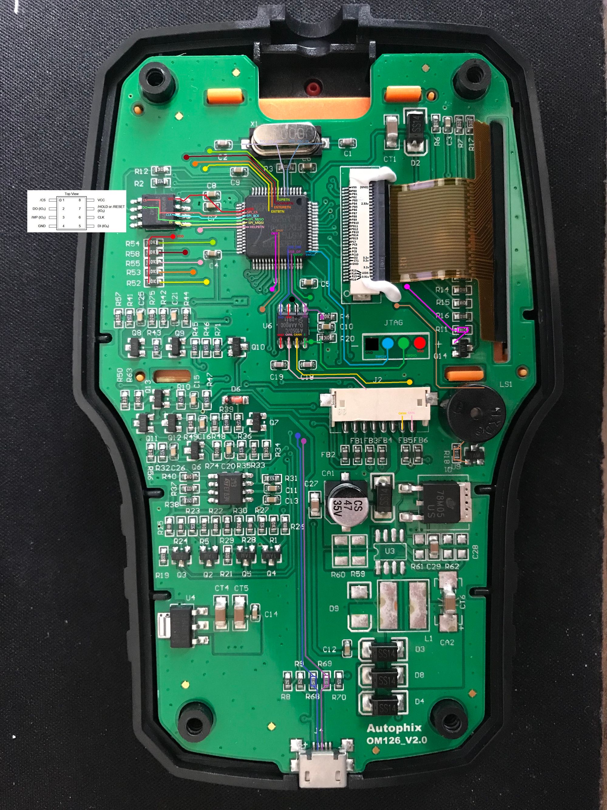
The beedy eyed mofo's out there have probably noticed that the silkscreen says this is "Autophix OM126_V2.0"... Another white labelled device sold under different names. you can get the original firmware here:

I only had a cursory glance at the Original Firmware, but from the off it looks encrypted (research for another day)
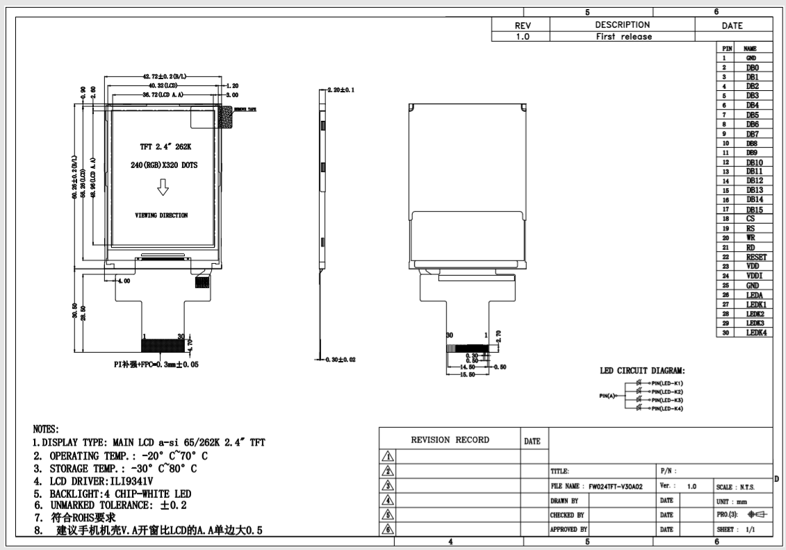
The thing here was the color screen. It had alot more pins than any other devices id previously looked at. I did some google foo with the silk print on the screen, and a company came up (ForWorld LCD (fwlcd.com), so i emailed them and the manufacturer of the device (AutPhix.com)
Here are the responses:
AutoPhix:
Dear customer,
Thank you very much for your email,we give you this part number is meaningless, this screen is not sold in the market.If your screen is broken, please contact your dealer.Have a nice day.
Best regards
ForWorld:
Hello,
What kind of products do you make?
please provide your company's contact information.
Regarding the 2.4-inch specification, I will provide the specification as soon as possible.
Thanks
Not a complete loss, and if/when it turns up, ill update this post
UPDATE: For anybody that is bothered, i know i am, here is the datasheet for the screen
So also a this time, the device I stuck with turned up!
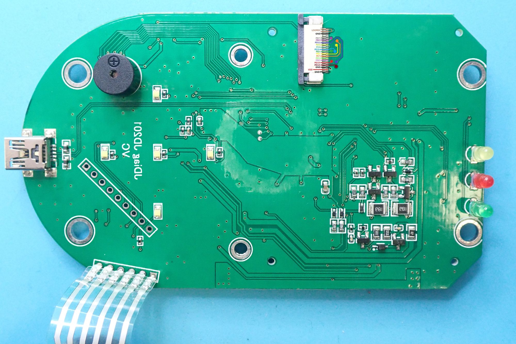
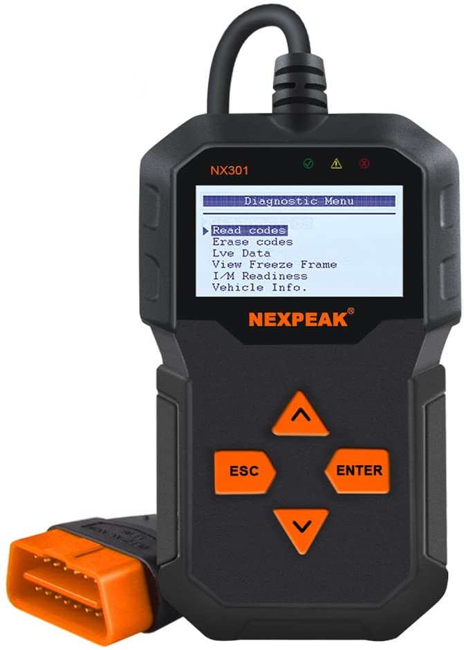
JDiag JD-101, made by the same company as the very first device i bought, so i thought id be in luck here!
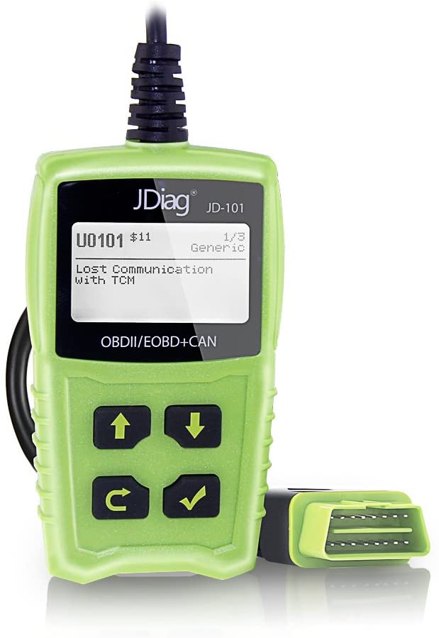
One thing to note here, is that although this is not a STM32 Chip, it’s a GD32 (basically a clone of the STM32) the same code would essentially work! The screen on this one had NO markings on it to try and get a pinout, or idea how to get it working without code! Again, this device had CRP, so we fucked out of luck here!
Ok So what does this device give us?
128x64 Non Color LCD Screen
4 Buttons
128Mb (16M x 8) Flash Storage
CAN Transceiver
USB capability
The first thing i did before anything else was to map the PCB traces out, and see if i could figure out the screen
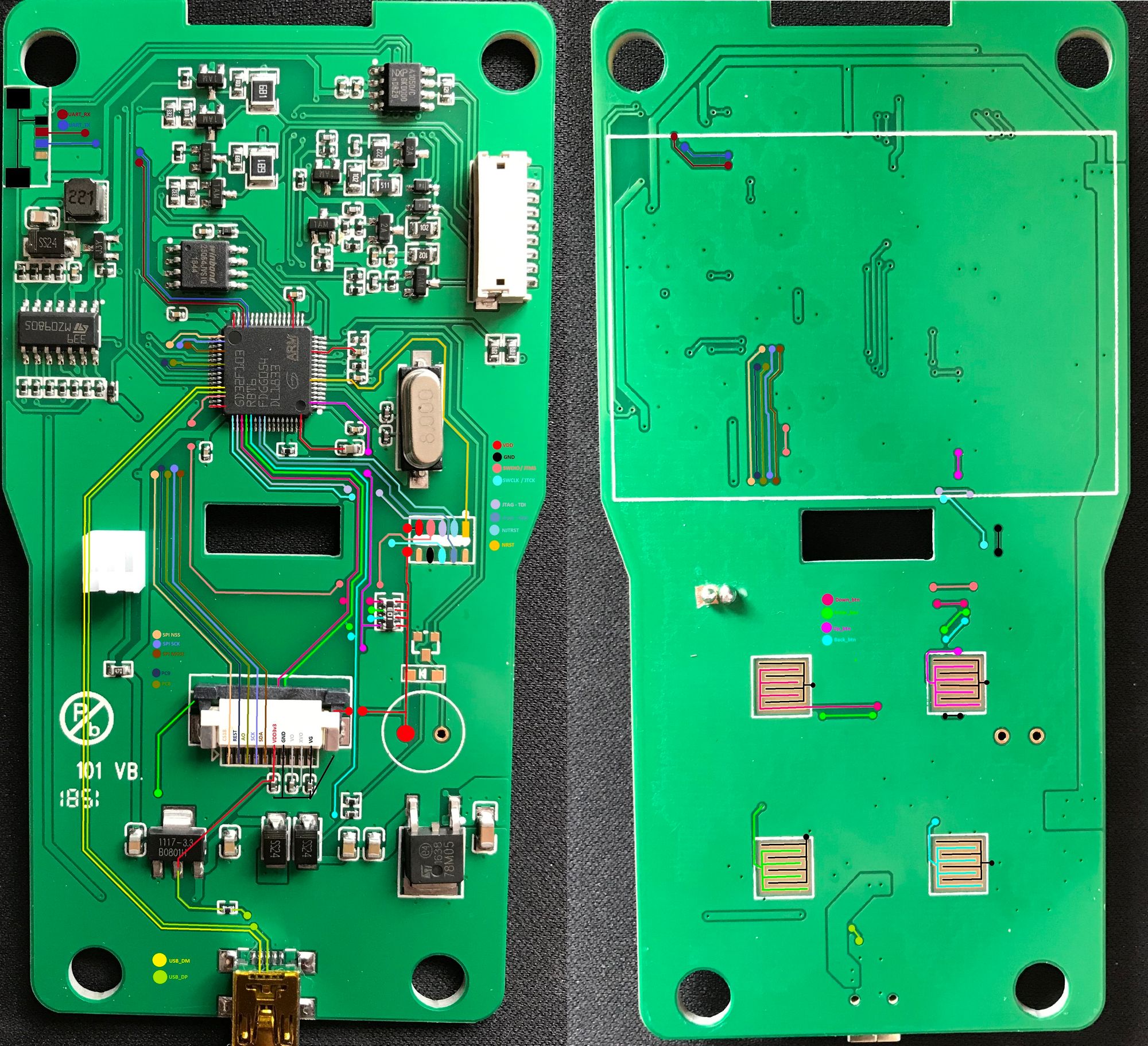
All quite simplistic? Yes i thought so too. How did i get the screen pinout? im glad you asked.
I noticed that the screen had 10 pins, and 2 for the LED's... On the IsYoung device, the pin count was exactly the same. SO... i swapped the screens between the devices and they worked! Winner. So i knew the pin out as it was silk screened onto the IsYoung.... GENIOUS!
Now that i knew 90% of the pins i wanted. its time to move on to the next stage!
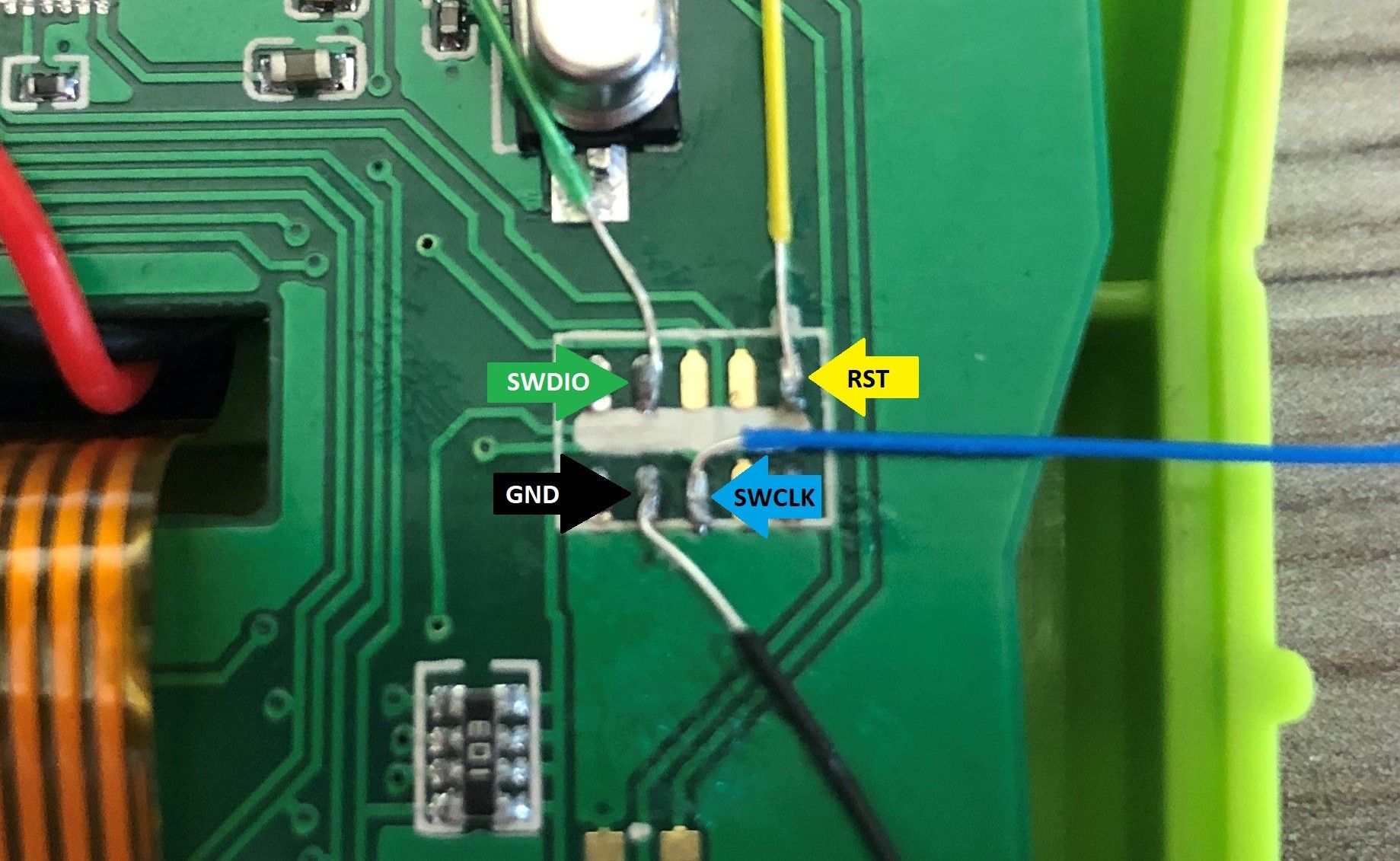
Let’s see how/if we can connect to this device with the SWD...
In fact, we can!
You need to use a SWD/JTAG debugger device depending on how the device is set up but, in our case, its SWD, so a ST-LinkV2/J-Link will do lovely!
By using STM32Cube-Programmer application, we can use the ST-Link to connect to the device. Like I said before, the device had CRP enabled, so I had to do a full chip erase to get the device to play!
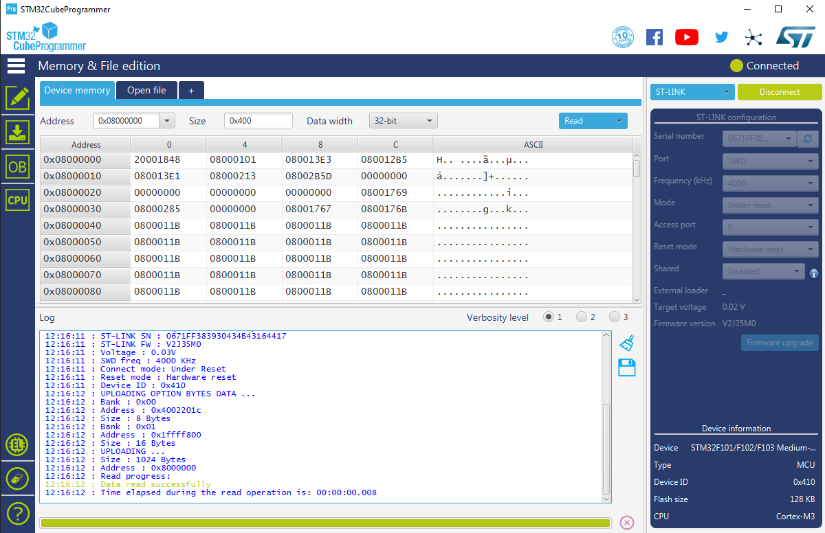
So now that we can load our own firmware on to the device, let’s have a thing about what we want to do with it?
Do i:
Write Tetris game for it
Turn it into a USB HID emulator/Attack Tool
A CAN bus Fuzzer! etc...
There are quite a few things you can do with STM32's, just do a google on STM32 projects and have a look.
What we’re going to get into now is how to write your own firmware for this device.
This will entail more investigatory work on the electronics side, to trace and use The Buttons/The Screen/SPI flash/CAN Transceiver, etc...
How you create a STM32 Project
What code is needed for use the pre-built device!
Stay Tuned for Part 2 coming soon!
p.s. I’m doing my artistic wire tracing using PAINT! if anybody has a better suggestion for doing this on windows, then I’m all ears!