DEEP INSERT – Card Skimmer Research
This blogpost is a direct copy of previous research i have done at SensePost. The original post resides here: https://sensepost.com/blog/2017/deep-insert-card-skimmer-research/
This blog post is purely for archive purposes only
So I get a phone call from Daniel on a Wednesday night,
Stu, can you bring your hardware stuff with you tomorrow, I’ve been given a card skimmer that i want us to see what we can get from it.
So I get my bag ready with the hardware tools i have, RS232 to USB UART adapter, Saelea 8 Channel Logic Analyser, and numerous other components.
Thursday comes round and I’m eager to see what device Daniel has, he gives me it and says “gimme 10, then we will sit down and see what we can get”, I waited 1-second and tore into this thing!
At each stage I will try to break down the “what, why, when, where, etc…” as much as i can, this was a great learning opportunity for myself to further my knowledge in hardware analysis.
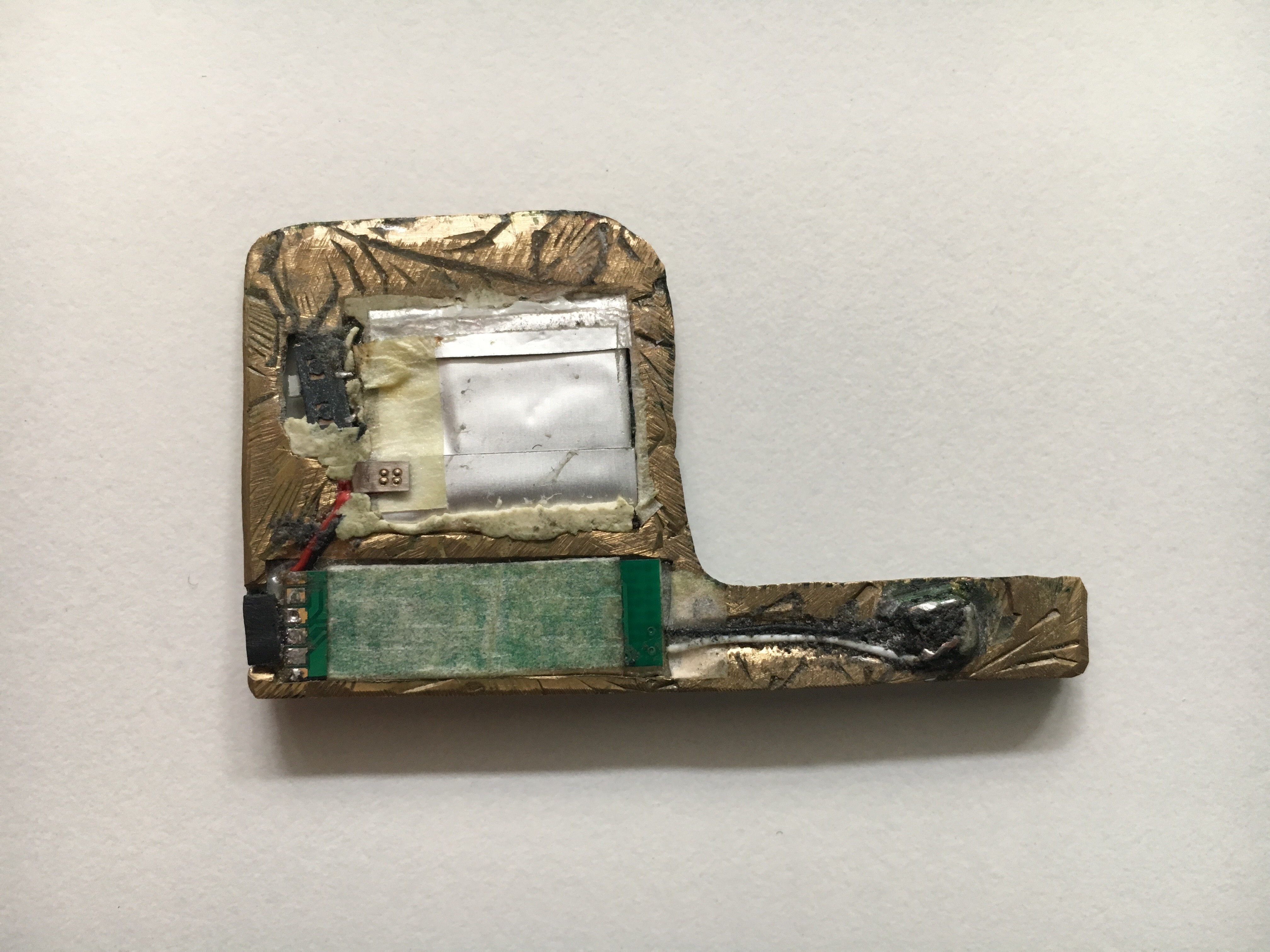
This is the bottom of the card reader, as you can clearly see it has a switch, a connector, some kind of PCB and a Analog Mag strip reader. most parts that are conductive are covered by masking tape. Taking a closer look at the “Brass” holder, it looks to be some kind of engraved brass picture frame or plaque, some parts even look filed to shape by hand for better fit into the machine and some parts are just super glued into place (wires).
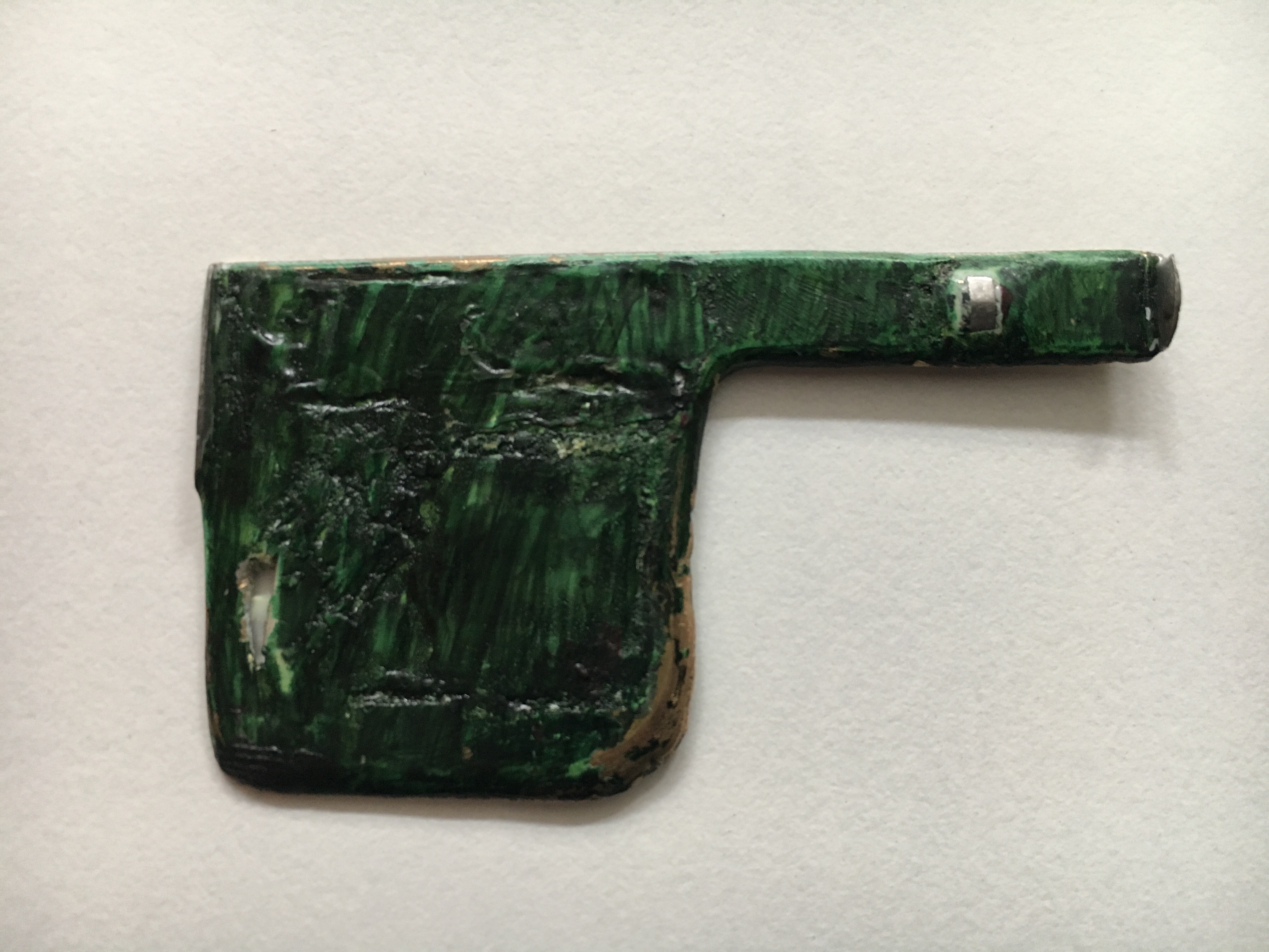
This was the top of the card reader and as you can see the mag strip reader is clearly visible. The rest of the device looks to have been covered in “Tipex” and then painted with some kind of green marker. Very rudimentary, very effective.
So taking in what I’ve just seen, even before Daniel could sit back down, I already had the PCB board out and stripped of the masking tape so I could see what chip-sets we are dealing with.
Identifying the chip-sets give us a better insight into what the board is trying to achieve and what capabilities it may have, also any kind of debugging that is available to use.
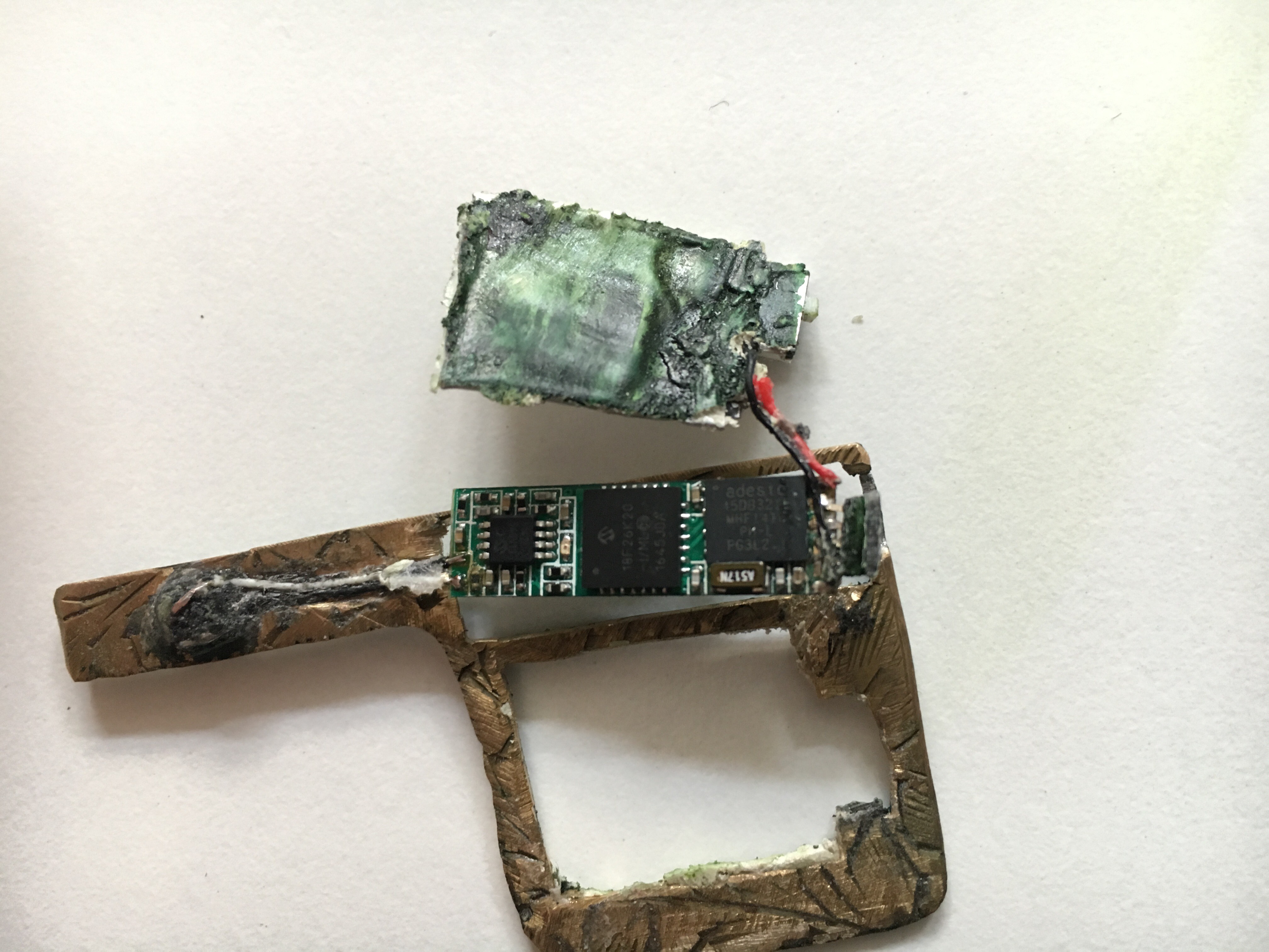
So far I have manage to keep everything intact apart from having popped the battery, it started getting slightly hot….
On this note, do not, for the love of god, get the juice that comes from these on your skin, it will burn and cause issues, also don’t swallow or rub it in your eyes, you will know about pain if you do!
Now that we have the masking tape off the PCB, we can now see the serial numbers and markings on the IC chips that exist on the board.
Further investigation shows there is a 4 pin plug on one end of the board with the Positive and Negative terminals situated either side of it.
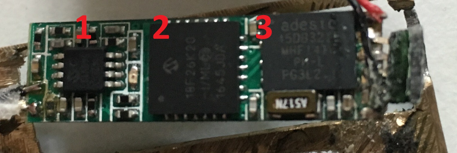
Let’s break down each chip-set and what it does. Hopefully getting a better idea of how and what this device is doing, what we can play with and hopefully what we can get into.
1: MCP6142 – a dual 600nA op amp.
http://www.microchip.com/wwwproducts/en/MCP6142
This is the closest IC I have found that contains the lettering that is stamped on the chip. It has the “Microchip” Logo, so there is a starting point, then there are two lines of text, one says “61421” and the other says “540V1J”….
After googling the life out of these, the closest thing was the chip linked above.
I believe this is being use as a voltage amplifier for some of the other micro controllers or even to be able to charge the LIPO Battery
More info can be found here https://en.wikipedia.org/wiki/Operational_amplifier
2: PIC18F26K20 28-pin QFN/UQFN
http://www.microchip.com/wwwproducts/en/PIC18F26K20
http://ww1.microchip.com/downloads/en/DeviceDoc/41303G.pdf
This is the brains of the board and will have the custom code (written in C probably) that grabs the mag strip data and stores it on the other chip (#3) in, possibly, a CSV/Tabled format. This should be easy to extract, but this does have capability to use hardware encryption of the data :(
3: AT45DB321E, 32-Mbit DataFlash – SPI Serial Flash Memory
https://www.adestotech.com/wp-content/uploads/doc8784.pdf
This is there the data is stored. 32MB of storage and very low operating voltage, perfect for these kind of situations. Minimal size, low power usage, plenty of storage!
So the board itself is quite unique and very very small. This board looks to be not purpose built but built on mass for a “analog” interface market.
Taking a step back!
Let’s get a list of info we have:
- Magstrip reader (2 wire, single track)
- Lipo Battery (rechargeable)
- Micro controller
- 32MB flash storage
- 4 pin connector
At this point, I think it best to take you (the reader) on a little journey into how mag strips actually work, so you get a better understanding of why this hardware exists.
MagStrips and Readers:
Magstrips:
“A magnetic stripe card is a type of card capable of storing data by modifying the magnetism of tiny iron-based magnetic particles on a band of magnetic material on the card. The magnetic stripe, sometimes called swipe card or magstripe, is read by swiping past a magnetic reading head. Magnetic stripe cards are commonly used in credit cards, identity cards, and transportation tickets.”
Thanks Wikipedia!
We’ve all seen and used these, especially if you have ever visited the States before.
Mag Readers:
“A tape head is a type of transducer used in tape recorders to convert electrical signals to magnetic fluctuations and vice versa. They can also be used to read credit/debit/gift cards because the strip of magnetic tape on the back of a credit card stores data the same way that other magnetic tapes do. Cassettes, reel-to-reel tapes, 8-tracks, VHS tapes, and even floppy disks and modern hard drive disks all use the same principle of physics to store and read back information. The medium is magnetized in a pattern. It then moves at a constant speed over an electromagnet. Since the moving tape is carrying a changing magnetic field with it, it induces a varying voltage across the head. That voltage can then be amplified and connected to speakers in the case of audio, or measured and sorted into ‘1’s and zeroes in the case of digital data.”
Some heads come with one, two or three heads. On this board, there is a single head of approx 2mm.
Thanks again Wikipedia, you smart bastard!
So the two parts that make these devices viable are:
1: credit/debit/store cards have mag stripes on them (#1 on the pic below) that contain a wealth of information.

2: Mag reader

The Mag Reader on the skimmer is a lot smaller than this, but you get the idea!
When you swipe, you give the card reader a tonne of info that can essentially take your cash and emulate your card elsewhere!
In the UK we have Chip and Pin and even Swipe and Pin, but there are card skimmers that can be used in conjunction with a number pad too.
Mag Strip Data:
There are up to three tracks on magnetic cards known as track 1, 2, and 3. Track 3 is virtually unused by the major worldwide card networks, and often isn’t even physically present on the card by virtue of a narrower magnetic stripe. Point-of-sale card readers almost always read track 1, or track 2, and sometimes both, in case one track is unreadable.
The minimum cardholder account information needed to complete a transaction is present on both tracks. Track 1 has a higher bit density (210 bits per inch vs. 75), is the only track that may contain alphabetic text, and hence is the only track that contains the card holder’s name.


Track 1 is written with code known as DEC SIXBIT plus odd parity. The information on track 1 on financial cards is contained in several formats: A, which is reserved for proprietary use of the card issuer, B, which is described below, C-M, which are reserved for use by ANSI Subcommittee X3B10 and N-Z, which are available for use by individual card issuers:
Track 1, Format B:
Start sentinel — one character (generally ‘%’)
Format code=”B” — one character (alpha only)
Primary account number (PAN) — up to 19 characters. Usually, but not always, matches the credit card number printed on the front of the card.
Field Separator — one character (generally ‘^’)
Name — 2 to 26 characters
Field Separator — one character (generally ‘^’)
Expiration date — four characters in the form YYMM.
Service code — three characters
Discretionary data — may include Pin Verification Key Indicator (PVKI, 1 character), PIN Verification Value (PVV, 4 characters), Card Verification Value or Card Verification Code (CVV or CVC, 3 characters)
End sentinel — one character (generally ‘?’)
Longitudinal redundancy check (LRC) — it is one character and a validity character calculated from other data on the track.
More on this can be found here
NOTE (I’m keeping this about the CC Skimmer, other cards such as driving licenses, library cards etc. have different formats)
Back to the Card Skimmer:
So we know that the card has magnetic data on it (like a cassette tape), we know the mag reader is essentially a microphone (takes the magnetic energy and converts it to voltage, voltage can be amplified for output) in this case it’s 1’s and 0’s.
So this got me thinking, maybe I could find the manufacturer of these boards to see more info if its available.
This is how my google search history went:
- 32mb audio recorder
- 32mb flash audio usb
- 32mb flash audio serial
- analog audio recorder
- mag strip audio 32mb
- 32mb voice recorder analog
- and just about every variation that i could think about
A few tabs later, this popped up:
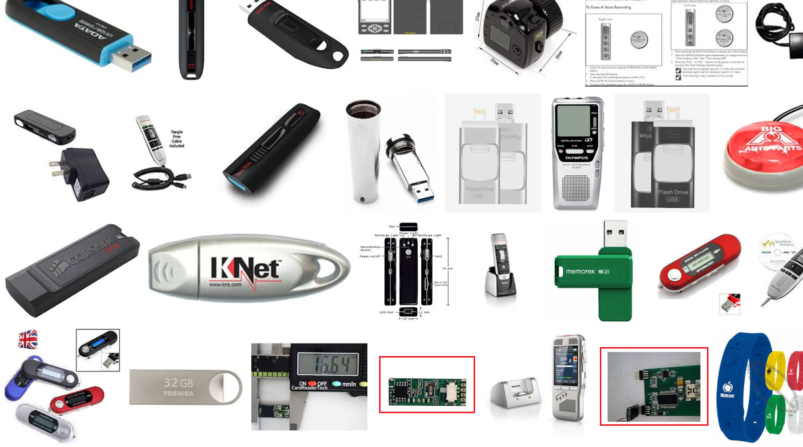
The two images bottom right and highlighted in red stood out as they have similar looking boards and pins, in actual fact, the pic on the left looks like it has the same MCP6142 – a dual 600nA op amp chip as was identified earlier. Let’s take a look.
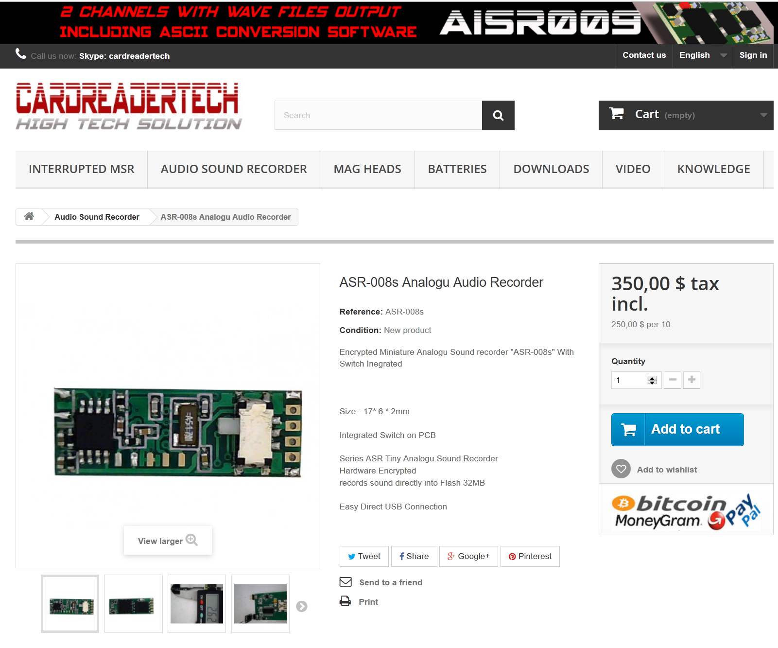
So it looks like I’m shooting at the correct target! Not the same board, but close, similar design and functions. Obvious DNS naming convention for your tech (http://www.cardreadertech.com) I suppose but look at the name of the product. “ASR-008s Analogu Audio Recorder”
Searching around the site, things start coming together:
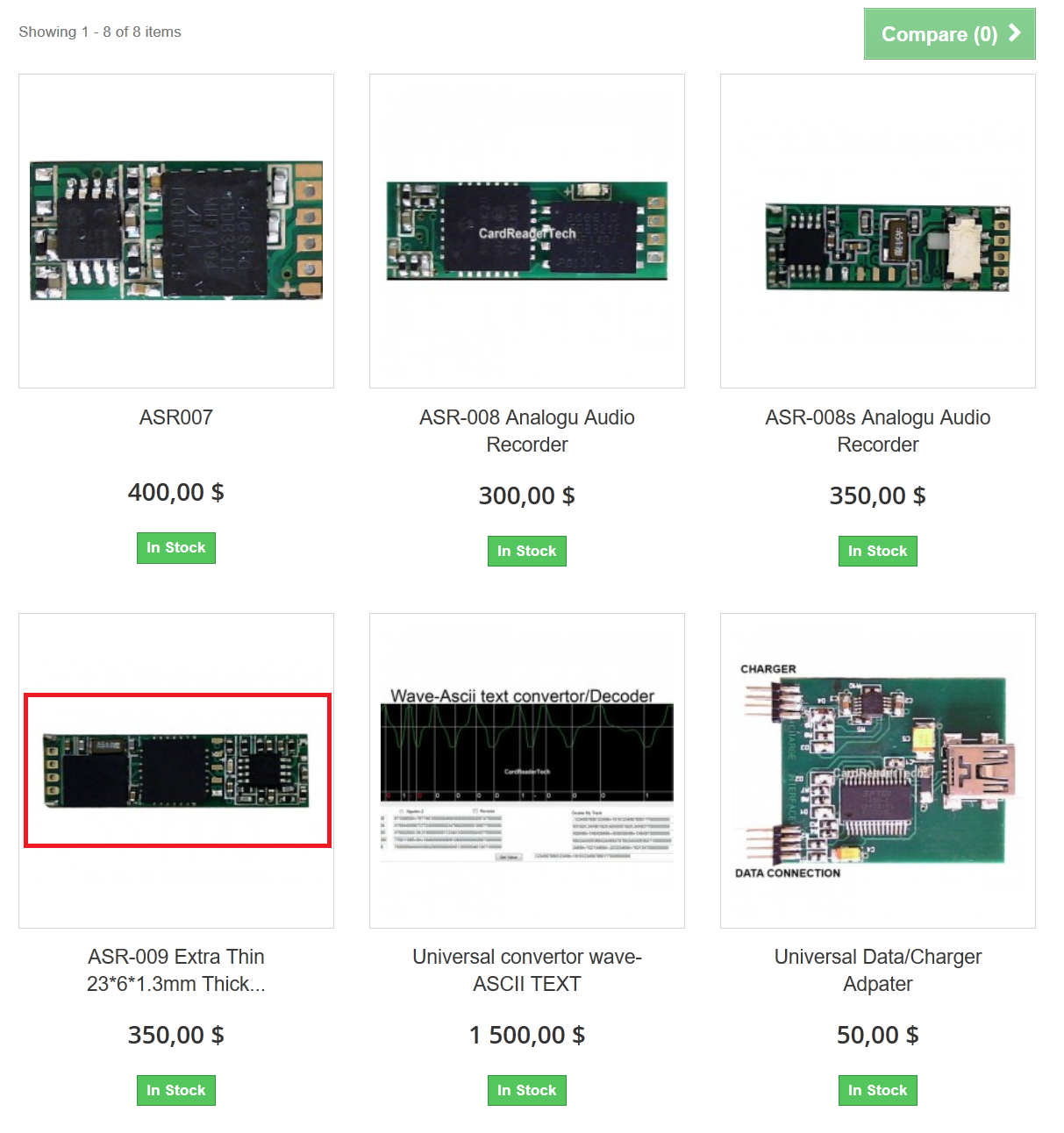
BINGO! This looks exactly like the board that we have.
Lets take a look. $350.00 is a nice price for essentially a lot of card data.
Data sheetThickness (mm)1.32Width (mm)7.05Length (mm)25.9Power consumption0.27mAh9mAh Battery Duration33hReading Tracks1 Mono ChannelSwipes stored8000Speed LimitationsAnalog No limits
Very small, very low power consumption and 8k swipes recorded, nice.
Specifications:
- USB Plug&Play connection
- Size – 23 * 6 * 1.3mm
- Ultra low power consumption ex: 40h with 9mAh 3.7V battery
- Flash Memory 32MB
- The format of the file system – Flash
- Encrypted Sound File
- Sound Sampling 10000Hz,
- Bit analog File .
- Voice activation selection (VOX)
- Current consumption When Standby Mode – 0 mA, the recorder is turned off Automatically as User selection between 5-200 sec
- The average current consumption in the recording mode – 0.53-1.7 mA,..
- Current consumption in standby mode, start recording at Sound activation above a certain Sound Wav – 0.01 mA
- Current consumption LED when Device is turn on 0.53 mA
- Power Source from 2.6-3.7V. other power Ranges than that will damage device.
The parts that interest me the most are:
- USB Plug&Play connection
- Encrypted Sound File
Lets move forward!
Grabbing the Data:

I’m not sure why its referencing the ASR-008 product but it is, and it says its a USB connection. So its USB, GREAT!, but what are the pin outs? As you can see from the product page, it plugs into a universal USB reader.

But, it says it’s direct USB plug and play. Confusing. Also, it operates on 3.7V, while USB is 5v. I don’t want to damage the data or the board, and it gives a link to the FTDI Drivers. If you look at the pic above, its a FTDI chipset. Ok let’s buy a USB FTDI cable :D
http://uk.farnell.com/ftdi/ttl-232r-3v3/cable-usb-to-ttl-level-serial/dp/1329311

WOOOOOOT!!!!
The Data:
I was able to recover a 28.4mb WAV file, this will need decoding. If you go here: https://www.dropbox.com/s/mdqotdbb0jbh7je/ASR00x-PCSoft.zip?dl=0
PWD: cardreadertech4312
You can use this to connect to the device and extract and decode the wav file just leaving you with the required card data.
NOTE: NO CARD DATA WILL BE PUBLISHED!
Further Research:
You cant really step into this world without finding a lot of references to Brian Krebs research on CC Skimmers, and he has released a lot of great into how the criminals are using these. Brian, if you read this, kudos and thank you. (p.s.) i also linked to some of your images.
https://krebsonsecurity.com/all-about-skimmers/
More specifically the card skimmer we had been given was classed as an INSERT card skimmer, although the tech used is very very similar for the surface mount skimmers.
Insert skimmers generally slot inside the existing card slot and fit where there are crevices minimizing the stress on the card and the machine. below are a few examples of INSERT Skimmers

This one looks near identical to the one we have but they do vary

Purpose built metal chassis, grooved and hand bent for ATM machines.
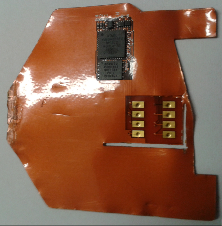
this skimmer is designed to read chip enabled cards and can be inserted directly into the ATM’s card acceptance slot, again very very thin, very fragile.
DEEP INSERT skimmers go further into the machine, behind the shutter mechanisms and away from viewing eyes.

Other Sellers, Markets and Devices:
http://www.dhgate.com/product/msr-card-reader-full-version-with-3mm-2-tracks/244634191.html
CONCLUSION:
This has been a great project to get stuck into. For me it shows how rudimentary things can be.
Also showing how in security, we tend to be slightly behind the curve when it comes to the criminal aspect.
After doing this research I find myself checking every ATM, trying to pull panels off, checking inside the card slot and generally looking very suspicious to other people. That being said, I would rather it be like that and not use a compromised ATM.
The device has now been handed off to Stephen A. Ridley for further analysis on the micro controller chip set.
