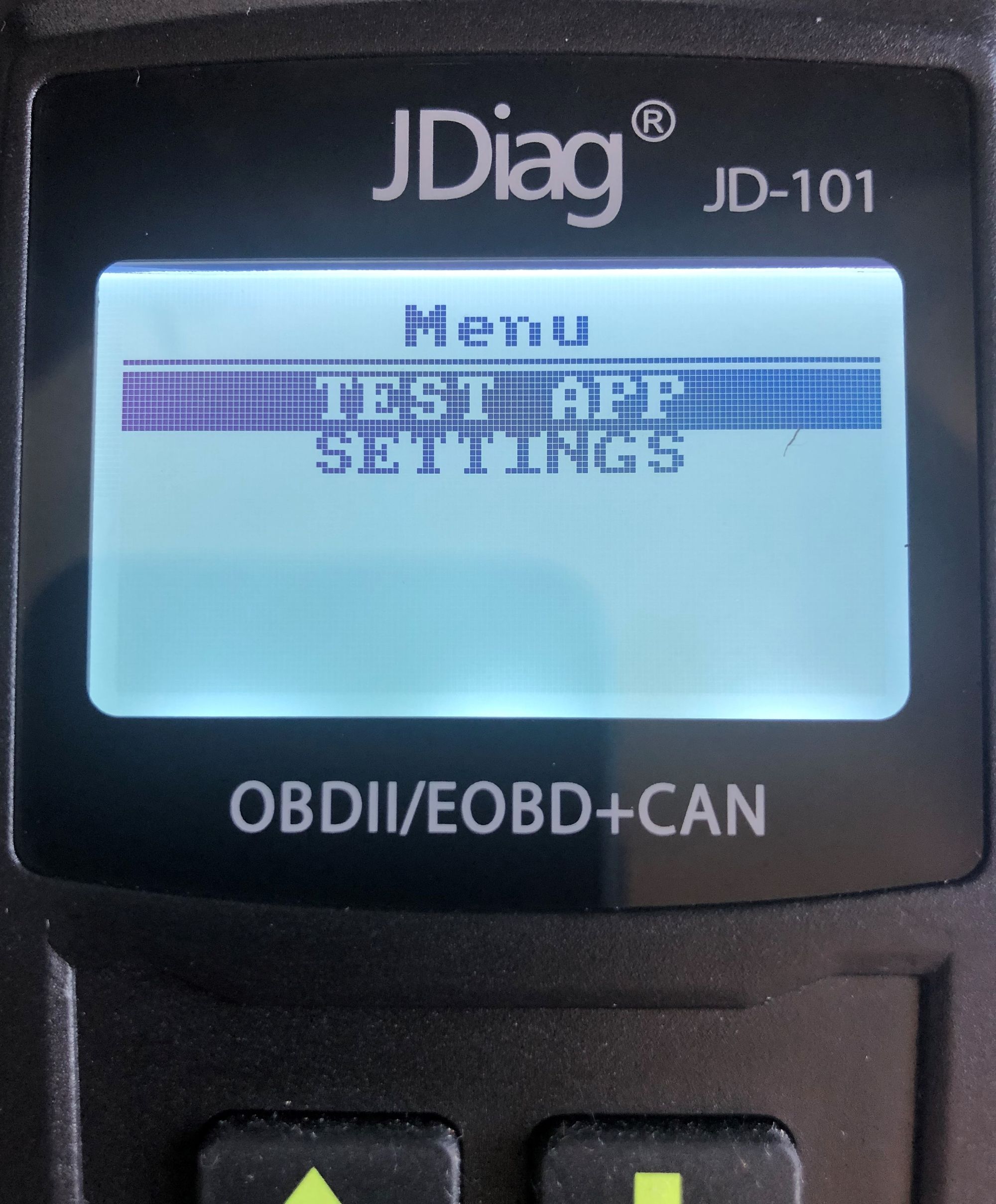
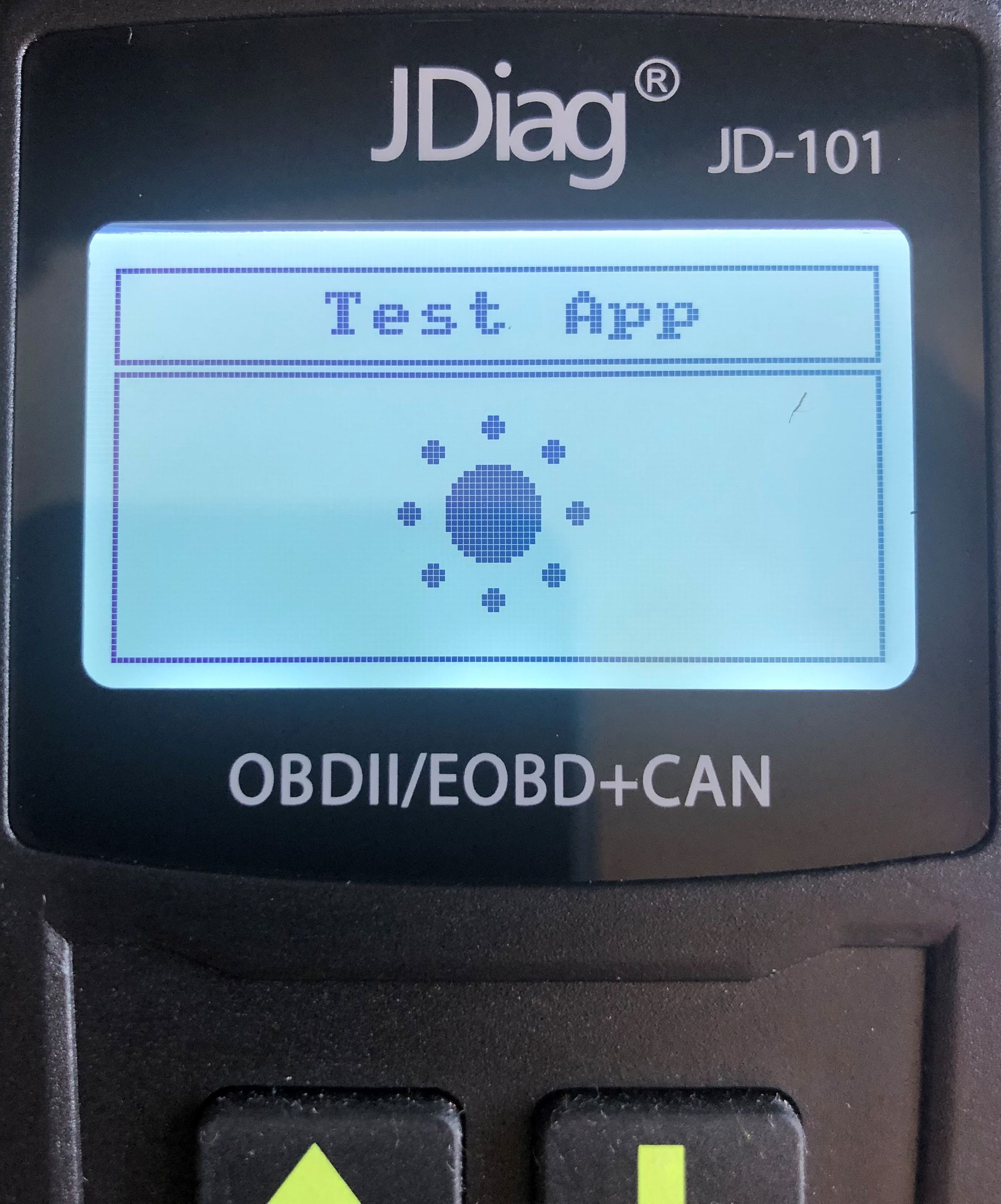
OBD2 Reader; Redesigned... Part 4 - Putting it all together!

So here we are, released public code for you (if you want) to take this device and repurpose it however you want.
I feel ive done what i wanted with this and to be honest. i have other things that id like to get done. However i will create a OpenSource version of an ODB2 diagnostic tool for this reader at some point. This project has now gone to the "as and when" pile ;)

Its been a great project and fun to learn bits and pieces from it.
Please enjoy the code and as always Feedback is always welcome!
NoobieDog/JD101
JDiag JD101 ODB2 Diagnostic Reader Custom Firmware - NoobieDog/JD101
Things that work in this version:
LCD Sreen:
  CLK = PB13
  DATA = PB15
  CS = PB12
  DC = PC8
  RST = PC9

Buttons:
  Down = PC10
  Up = PC13
  Enter = PC11
  Back = PC12

USB Serial Console:
  CDC - USB

SPI flash Memory:
  MISO = PA6
  MOSI = PA7
  CS = PA4
  Clock = PA5
Things that DONT work in this version:
ODB2 Connector:
  CAN High = PB9
  CAN Low = PB8
  K-line = ?
  L-Line = ?
  SAE + = ?
  SAE - = ?

Voltage
  PIN = No Idea

Crystal Osc
  RCC_OSC_OUT = PD1
  RCC_OSC_IN = PD0

Additional USART (unpopulated USB connector on PCB)
  RX = PB11
  TX = PB10